
On this page
A leaking or distorted rubber expansion joint needs a clear field record before anyone assigns a cause. A wet flange, a damp rubber body and a flattened arch are different observations. Each calls for a different check. Appearance alone cannot establish whether the problem began with the joint, its installation or the operating system.
This guide helps maintenance and engineering teams document what they can see, identify findings that need prompt action and prepare a useful technical review. It does not replace the site’s isolation procedure or the selected joint’s approved drawing and instructions.
1. Find where the leak begins
First determine whether fluid is coming from the connection between a mating flange and the joint, or from a surface of the rubber body. Fluid can run along a flange or pipe and drip somewhere else. Record the first visible wet point, take an overall photograph and then take a close-up that shows its location. Note whether the leak appears during startup, steady operation or shutdown.
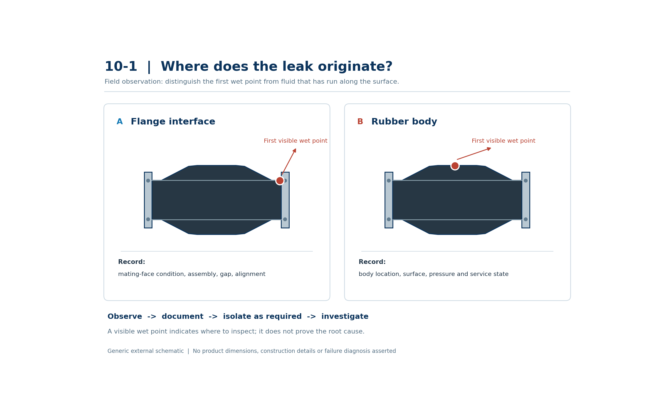
Figure 1. The first visible wet point directs inspection toward the flange interface or the rubber body. The schematic identifies an observation, not the root cause or an internal leak path.
At a flange interface, check the sealing faces, the support behind the rubber end, the bolt assembly and the installed position against the approved drawing. Do not assume that tightening bolts will cure every leak. Any adjustment must follow the site’s pressure-isolation procedure and the manufacturer’s assembly instructions. For the connection details, see Rubber Expansion Joint Flange Connections: Sealing Faces, Backing Support and Bolt Assembly.
Leakage through the rubber body is a different finding. Take the joint out of service under the site’s procedure and arrange a replacement assessment. An external patch should not be treated as proof that the joint remains suitable for service.
2. Measure the installed position
An arch may look stretched, compressed or uneven. To investigate, compare the actual piping geometry with the selected joint’s specified installation position. Record:
- The distance between the mating flange faces, measured at the 12, 3, 6 and 9 o’clock positions where accessible and safe.
- Horizontal and vertical offset between the flange centres, and whether the faces are parallel.
- The location and condition of nearby supports, anchors, guides and any control units.
- The drawing and revision used for the specified dimensions.
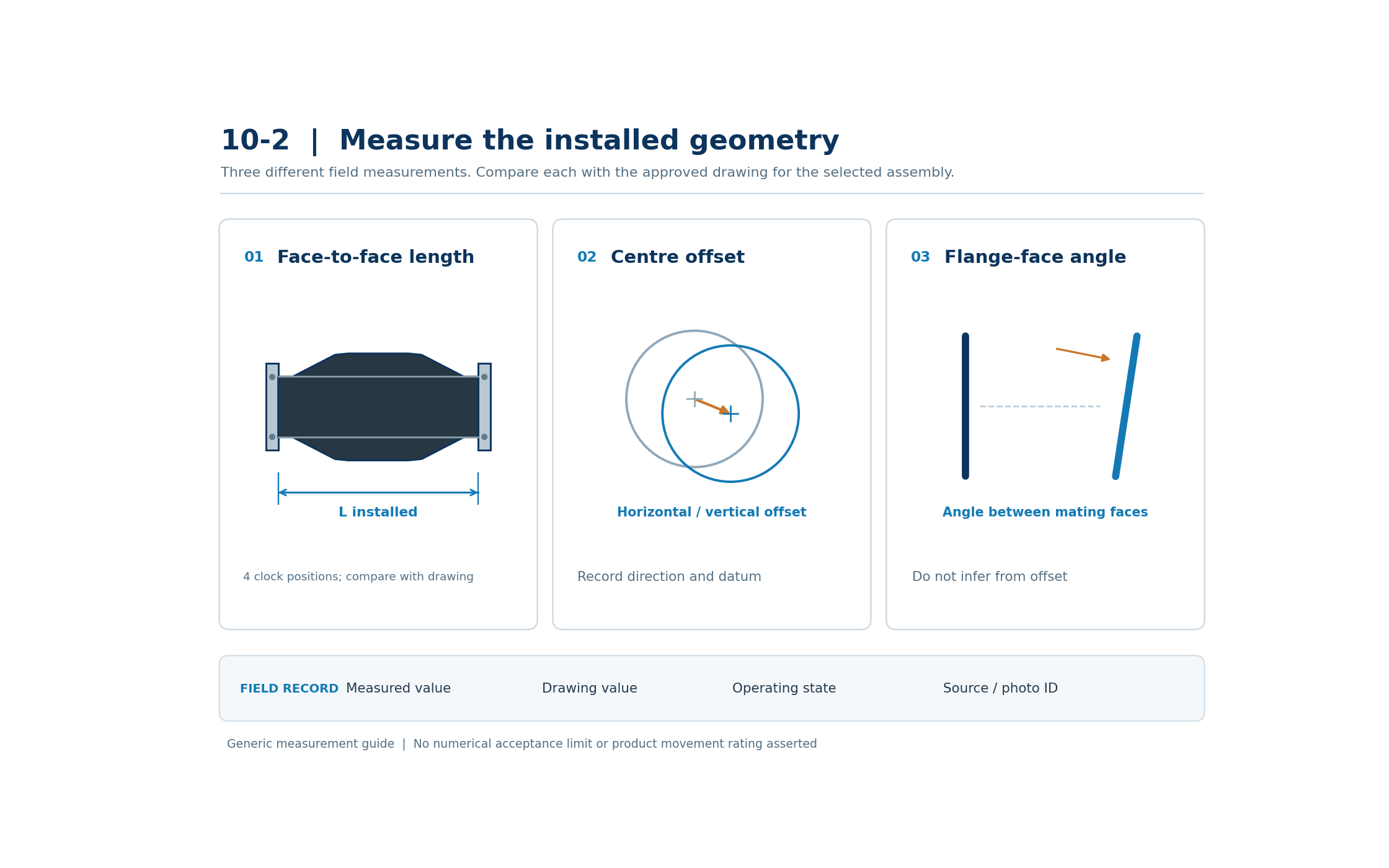
Figure 2. Face-to-face length, centre offset and flange-face angle are separate measurements. Record the operating state and source of each value. The sketch does not give an acceptance limit.
A mismatch is evidence for review, not a diagnosis by itself. The piping engineer should compare the cold installed position and operating movements with the selected assembly’s approved data. The difference between those positions is explained in Combined Movement in Rubber Expansion Joints: Installation Offset and Operating Displacement.
3. Describe the rubber condition precisely
Record where cracks, blisters or changes in shape occur and whether they have grown since an earlier inspection. Photograph the arch, the base of the arch, the flange area and any visible damage to the inner tube during a properly isolated inspection. State whether fabric or metal reinforcement is exposed.
Fine cracks limited to the outer cover do not, by themselves, establish that the joint has failed. Exposed or torn reinforcement, significant inner-tube separation and leakage through the body are more serious findings requiring prompt action. A visible blister should be documented and assessed; its appearance alone does not prove internal separation.
4. Use the observation to choose the next check
| Field observation | Check next | The observation alone does not prove |
|---|---|---|
| Fluid at a mating flange | First wet point, sealing faces, support, bolts and installed length | That bolt torque is the cause |
| Fluid from the rubber body | Exact origin, body condition and operating state; arrange safe withdrawal and replacement review | What initiated the damage |
| Flattened or uneven arch | Approved length, installed dimensions, offset and operating movement | That a particular movement limit was exceeded |
| Blister, crack or exposed reinforcement | Location, depth, inner-tube condition and change over time | That all visible marks have the same severity or cause |
| Failure repeated after replacement | Previous and new drawings, alignment, restraints, medium and pressure history | That fitting the same replacement again will solve the problem |
This table directs an investigation; it is not a product acceptance standard. Keep what was observed separate from what is suspected. Mark missing values as unknown rather than filling them with typical catalogue figures.
5. Compare the findings with operating history
Collect the medium and any cleaning chemicals, normal and design pressure and temperature, minimum pressure where relevant, and the sequence of pump starts, stops and valve operations. Record when the symptom was first noticed and whether it changed.
If a transient event is suspected, obtain the pressure history at the joint location. Appearance alone cannot establish that water hammer caused the damage. See Water Hammer and Rubber Expansion Joints: What a Transient Analysis Must Confirm for the system information needed.
The final review should identify the actual joint model and construction, drawing revision, installed position and service conditions. Confirmation for one assembly does not automatically apply to another size, material or customer-specified configuration.
Field record to send for review
Send the joint’s location and markings; overall and close-up photographs; the first visible leak point; measured flange distances and alignment; medium, pressure and temperature; the event timeline; a sketch of supports and restraints; and the approved drawing if available. Separate observed facts, measured values and unknowns.
Mingchao Fluid Technology can review a replacement or a drawing-based configuration against the information supplied. Dimensions, construction and allowable service conditions must be confirmed for that particular assembly. See our Technical Information & Engineering Resources and rubber expansion joint product range.