
On this page
- Start with the expansion joint’s end construction
- Locate the actual sealing surface
- Check what supports the rubber end
- Verify flange drilling with numbers, not names alone
- Review the complete bolt assembly
- If the flange leaks, establish where the leak begins
- Information to include in a flange connection review
- Technical references
Matching the nominal pipe size is not enough to establish a sound rubber expansion joint flange connection. Even when the bolts can be inserted, the assembly must still provide the intended sealing contact, support the rubber end correctly and apply the clamping load through the appropriate components.
These are three related but different checks. A flange dimension table helps establish whether the holes and connection sizes correspond. It cannot, by itself, show where the rubber seals or whether the selected end construction has the backing support it requires.
This guide explains what to examine in the product drawing and at the mating flange. Final assembly details must follow the selected product and approved project drawing.
Start with the expansion joint’s end construction
Rubber expansion joints are supplied with different end constructions. Two commonly discussed arrangements are a full-faced elastomer flange supported from behind by a retaining ring, and a spherical joint with a beaded rubber end held by a suitable floating flange.
The distinction matters because the parts do different jobs. The rubber surface forms a seal against the mating flange. The retaining ring or floating flange supports the rubber end and helps transfer the bolt clamping load. The bolts hold the complete connection together. Treating all three as simply “the flange” makes it harder to identify an installation error.
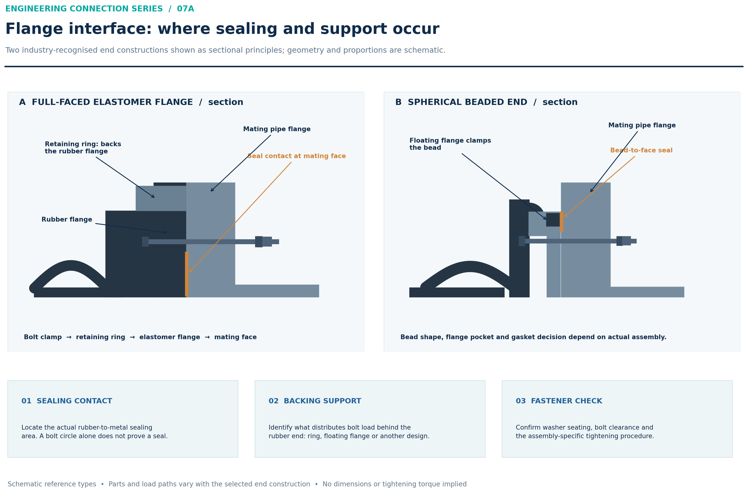
The diagram above separates sealing contact from backing support in two reference end constructions. Shapes and proportions are schematic; the selected product drawing determines the actual parts and geometry.
The Fluid Sealing Association technical handbook discusses retaining rings used behind rubber flanges and, separately, the beaded seals and floating flanges of molded spherical joints. Its descriptions are useful for understanding the principles, while its handbook also cautions that individual manufacturers’ products can differ.
Before using either illustration to specify an actual connection, identify the proposed product’s end construction from its approved drawing. A photograph showing a steel flange around a rubber body does not reveal every contact surface inside the assembled joint.
Locate the actual sealing surface
On the drawing, trace the boundary between the expansion joint’s rubber end and the mating pipe or equipment flange. That interface is where a leak-tight seal must be achieved.
Check whether the mating flange provides the required contact area and surface condition. Record its facing type and dimensions rather than describing it only as “DN100 flange” or “ANSI flange.” During inspection, look for damage, contamination or an obstruction within the intended sealing area. Also confirm that the two flange faces can meet in the position specified for installation; bolts should not be used to force an unsuitable pipe arrangement into place.
A flat face and a raised face present different contact geometries. Whether a raised face is acceptable, or whether any additional component is needed, depends on the actual expansion joint construction and its installation instructions. For example, one manufacturer’s published guidance permits particular raised-face conditions for its own joints; that statement cannot be transferred automatically to another manufacturer’s product. FSA guidance likewise directs users to confirm the applicable connection arrangement.
Do not add a gasket simply because the connection contains two flanges. Some rubber joint ends are designed to form the seal themselves. Other combinations may require a specifically approved arrangement. An extra gasket can change the position of the contact and the available support; it should be a drawing decision, not an improvised remedy for leakage.
Check what supports the rubber end
A sealing surface needs the intended support behind it so that the bolt load reaches the contact area in the manner assumed by the design.
For a construction using retaining rings, verify that the rings are present, correctly positioned against the back of the rubber flanges and compatible with the bolt arrangement. Where the rings are split, inspect how the bolts and washers bear near those splits. FSA installation guidance specifically addresses washers at retaining-ring splits and the effect their omission can have on flange leakage.
For a beaded spherical end, review the actual bead and floating-flange arrangement shown in the selected product drawing. The bead must be retained and clamped by the geometry intended for that design. A generic diagram cannot establish the dimensions of the bead, its recess or the mating flange contact area for a particular KXT or KST order.
Backing support should also be distinguished from a control rod or other piping restraint. A control unit may have an important role in limiting movement or carrying specified system loads, but its presence does not replace the need to check how the rubber end is sealed and clamped.
Verify flange drilling with numbers, not names alone
The flange outside diameter, bolt-circle diameter, number of holes and hole diameter should be checked together against the mating connection. The nominal size identifies the general pipe size; it does not make different flange standards interchangeable.
The comparison below uses DN100 reference dimensions published on Mingchao’s standards pages. The circles and bolt positions show why a connection cannot be accepted from a DN designation or an outside diameter alone. www.mingchaoft.com
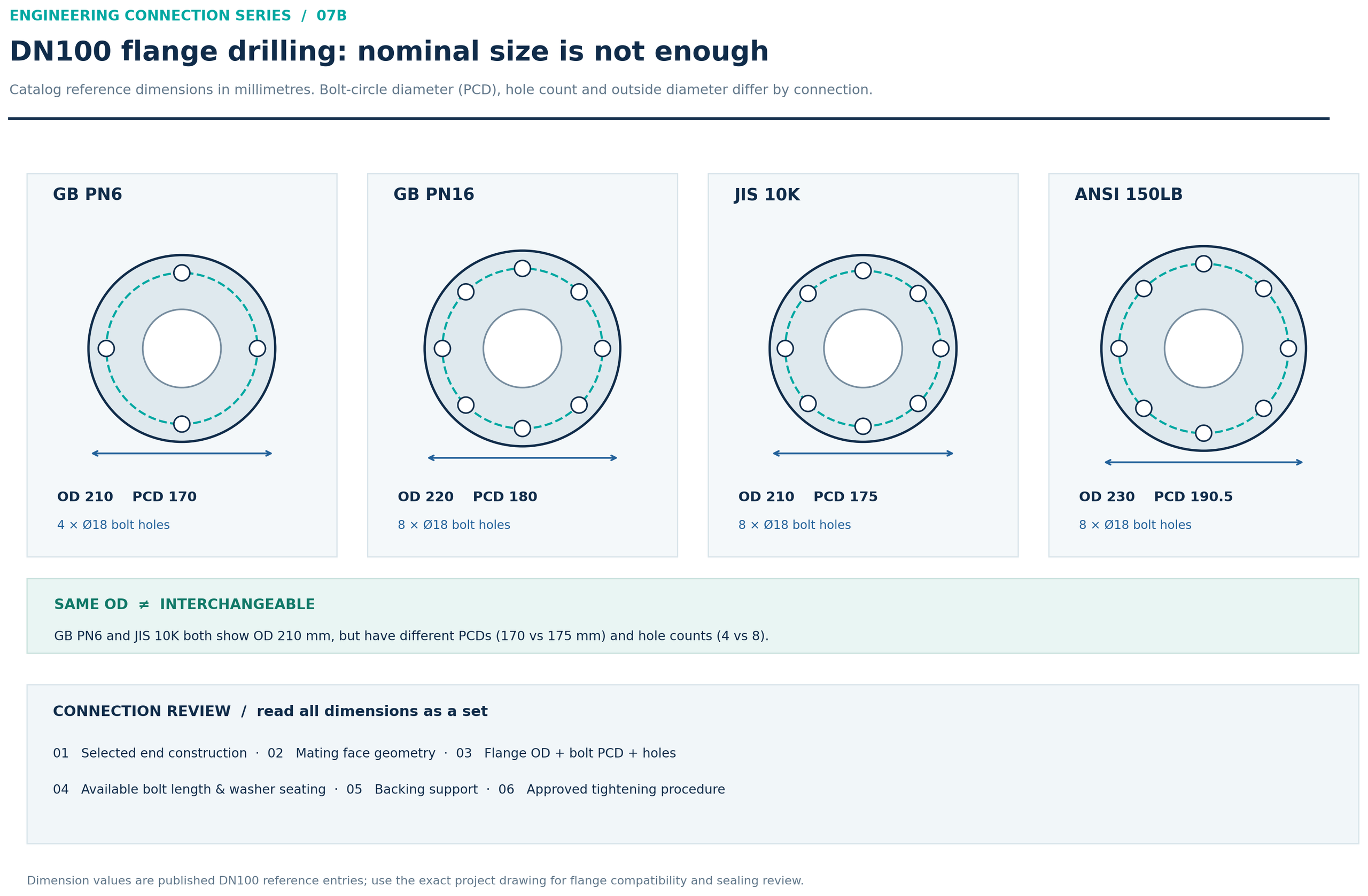
The diagram above compares published DN100 reference entries. Confirm the complete flange dimensions and the applicable approved drawing for the product being ordered.
One useful example is GB PN6 versus JIS 10K. Mingchao’s published DN100 entries give both an outside diameter of 210 mm, yet the bolt-circle diameters are 170 mm and 175 mm, and the hole counts are four and eight, respectively. Equal outside diameter therefore does not establish bolt compatibility.
The same dimensional review belongs in replacement enquiries. If an existing flange standard is unknown, provide its measured outside diameter, bolt-circle diameter, number and diameter of holes, and photographs of the connection. The flange facing and sealing contact still require their own check after the drilling is identified.
Review the complete bolt assembly
Once the connection geometry is established, inspect the hardware path from the bolt head or nut through the washer and supporting parts to the mating flange. The required bolt length must account for the selected joint end, mating flange and any approved additional components. Bolts must also be positioned so that they do not interfere with the rubber body during installation or movement.
Tightening should follow the approved procedure for the specific end construction and connected equipment. Mingchao’s published KXT and KST guidance calls for gradual, even tightening in a diagonal sequence. The FSA handbook provides different reference torque tables for different rubber-joint end constructions and expressly notes that mating equipment or flange materials may require different values. Its reference figures are therefore not a universal torque specification for Mingchao products. www.mingchaoft.com
A practical installation record should identify which product instruction or project procedure was used. Recording only “bolts tightened” leaves unanswered which sequence, components and acceptance criteria applied.
If the flange leaks, establish where the leak begins
A visible leak near a rubber expansion joint does not, on its own, identify the failed component. First distinguish leakage at the flange interface from leakage through the rubber body. For an interface leak, document its position around the circumference and inspect the corresponding sealing face, backing support, washers and bolt assembly under the site’s approved isolation and inspection procedure.
Uneven compression, a damaged mating face or an unsuitable contact arrangement may each warrant investigation. They should be recorded as possible causes to examine, not diagnosed from a photograph alone. Repeatedly tightening bolts without understanding the connection can obscure the evidence and may damage an elastomeric end.
This article concerns the flange connection. Broader diagnosis of rubber-body damage, abnormal deformation and in-service failure requires a separate inspection of the joint and piping system.
Information to include in a flange connection review
For a technical quotation, replacement or installation review, provide the following as a single connection record:
| Item | Information required |
|---|---|
| Expansion joint | Model, nominal size, selected end construction and drawing revision |
| Mating flange | Standard, pressure designation, facing type and material |
| Drilling | Flange outside diameter, bolt-circle diameter, hole count and hole diameter |
| Sealing interface | Intended rubber contact area and condition of the mating face |
| Backing support | Retaining ring, floating flange or other specified components |
| Fasteners | Bolt size and length, washer arrangement and clearance |
| Installation | Face-to-face distance, alignment and applicable tightening procedure |
| Evidence | Product drawing, mating-flange drawing and connection photographs |
If any entry is unknown, identify the gap in the enquiry. The final decision should refer to the selected assembly and its mating flange, rather than a generic DN size or an unrelated product illustration.
Mingchao can review a proposed connection against the supplied dimensions and operating conditions. Start with the relevant KXT single-sphere product page or KST double-sphere product page, and use the Technical Information & Engineering Resources page to prepare the project data.
Technical references
- Fluid Sealing Association, Expansion Joints—Piping Technical Handbook: reference end constructions, retaining rings, mating flanges and installation guidance.
- Mingchao DN100 dimension references: GB PN6 / PN10 / PN16, JIS 5K / JIS 10K and ANSI 150LB.