On this page
- 1. Distinguish Overall Length from Live Flexible Length
- 2. Define the Movement Before Selecting the Radius
- 3. Use the Applicable Static or Dynamic Bend Radius
- 4. Match the Routing to the Movement
- 5. Prevent Twisting and Protect the Connections
- 6. Submit a Geometry Record That Can Be Reviewed
- Applying the Review to a Mingchao JR Assembly
- Mingchao Product Information and Related Reading
- Technical References
A stainless steel flexible metal hose must fit the connection and accommodate the movement expected in service. Specifying its overall length alone does not establish either requirement.
The geometry review needs three linked inputs: the available live flexible length, the applicable bend radius and the positions of the two connections throughout operation. Pressure, temperature, materials and end loads then require their own confirmation.
This guide addresses braided corrugated metal hose assemblies, including flanged configurations such as Mingchao’s JR range. It provides a drawing-review method rather than a universal hose-length formula.
1. Distinguish Overall Length from Live Flexible Length
Overall length is the assembly dimension between specified end-connection datums. For a flanged assembly, the drawing should identify the flange faces used for that measurement.
Live flexible length is the portion intended to participate in bending. In a conventional braided hose assembly, it is commonly identified between the braid collars. The manufacturer’s drawing must establish its actual boundaries.
End fittings, connection necks and collar regions occupy part of the overall length. Changing those components can change the live length even when the ordered overall length remains unchanged.
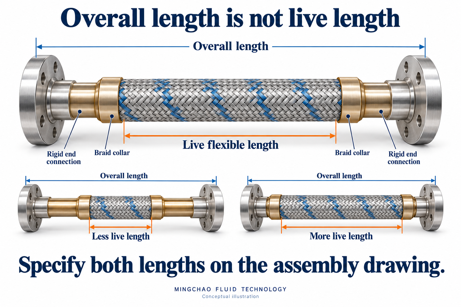
The illustration above distinguishes overall assembly length from live flexible length. Highlighted end regions identify connection components; the colour does not specify their material.
A simple example shows why both dimensions belong on the drawing:
| Dimension | Assembly A | Assembly B |
|---|---|---|
| Overall length | 600 mm | 600 mm |
| Left end region | 100 mm | 150 mm |
| Right end region | 100 mm | 150 mm |
| Remaining live flexible length | 400 mm | 300 mm |
These are assumed dimensions for straight assemblies measured along the same axis and between consistent datums. They illustrate length allocation only. They do not establish movement capacity, minimum bend radius or suitability for a Mingchao product.
For a curved installation, the distance between connections is not the developed length of the hose. Do not use the pipe gap as a substitute for either overall assembly length or live length.
2. Define the Movement Before Selecting the Radius
Describe what each connection does, rather than requesting a hose with “more flexibility.”
A fixed installation offset differs from a connection that moves repeatedly. Pump vibration, thermal movement and occasional equipment repositioning also impose different duties.
Record:
- The position and orientation of both connections at installation.
- Which connection moves, in which direction and by how much.
- The extreme operating positions.
- Whether movements occur together.
- The expected frequency or number of cycles.
Use one reference system for the complete record. A cold installation position and a hot operating position are useful only when both are measured or calculated from the same datums.
An initial offset is not necessarily free movement allowance. It already determines the shape in which the hose begins service.
3. Use the Applicable Static or Dynamic Bend Radius
A static minimum bend radius applies to the manufacturer’s defined fixed-installation condition. A dynamic minimum bend radius applies to specified flexing service.
A hose that can be bent into a fixed position is not automatically suitable for repeated movement at that radius. Conversely, meeting a dynamic radius requirement does not establish the assembly’s pressure capability or fatigue life by itself.
Confirm the radius for the selected hose construction, diameter, braid and service conditions. Also establish the measurement convention. Corrugated metal hose radii are commonly measured to the hose centreline, but the applicable product document governs.
Check the smallest local radius throughout the movement, including areas near the connections. A gentle-looking curve in the middle can conceal a tighter bend at one end.
Hose Master’s guidance also identifies vibration and large pressure changes as dynamic considerations. A visually stationary hose should therefore not be classified as static solely because no large movement is visible.
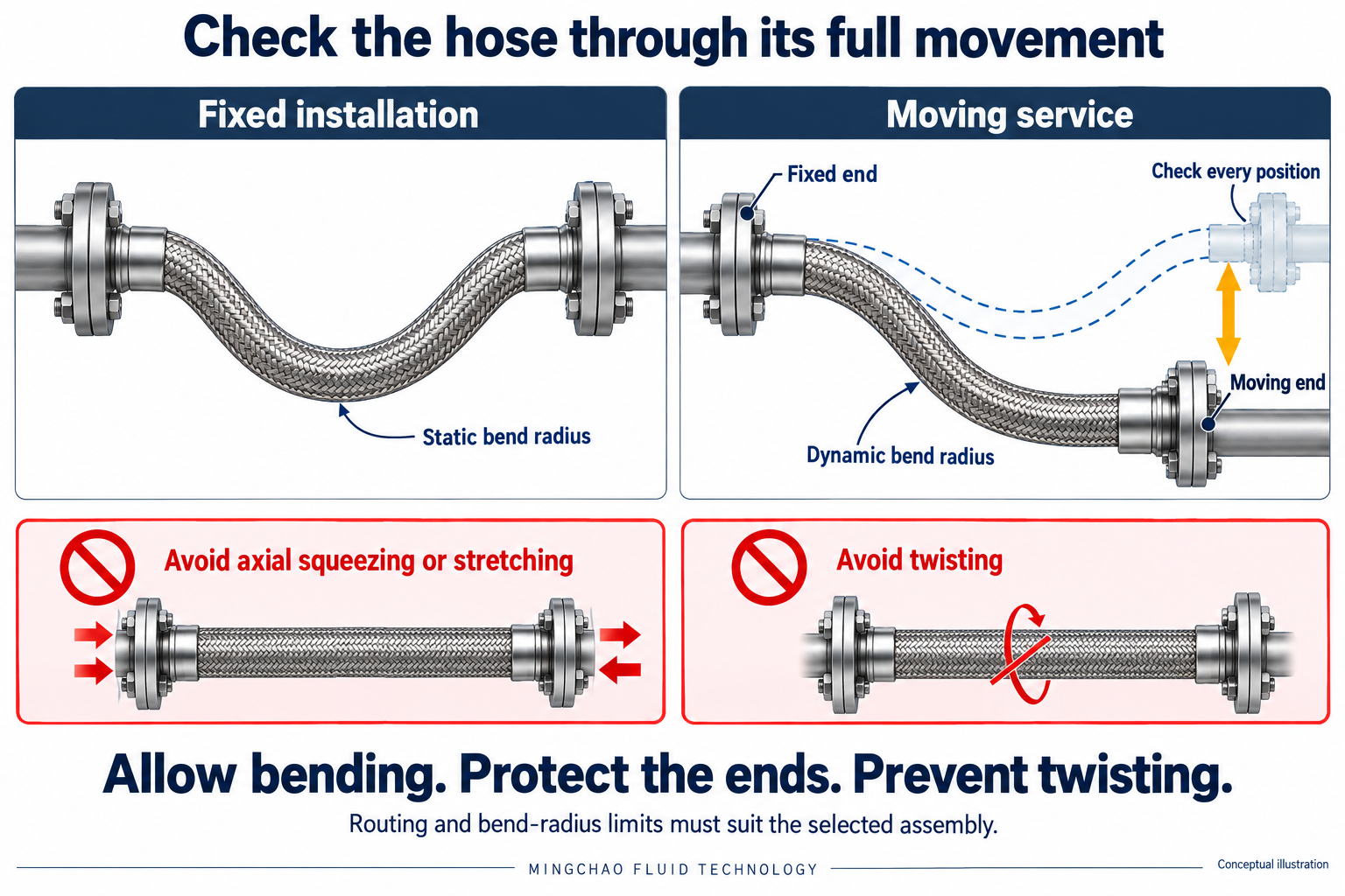
The illustration above contrasts a fixed configuration with moving service. The dashed outline represents another operating position. Radius labels identify the relevant review; they are not measured radii or approved installation limits.
4. Match the Routing to the Movement
The hose accommodates movement through an approved change in its curved geometry.
A straight braided metal hose should not be compressed or stretched axially to make it fit. Mingchao’s JR technical datasheet expressly distinguishes this restriction from the function of an axial expansion joint.
Where pipe movement would act along a straight hose’s axis, the designer should review a suitable hose-loop arrangement or another component intended for that duty. Adding slack without checking the resulting shape is not a routing calculation.
For each proposed arrangement, examine the complete movement envelope:
| Check | Question to resolve |
|---|---|
| Bending plane | Does the movement remain within the intended plane? |
| Curvature | Is the applicable minimum radius maintained in every position? |
| End regions | Does bending concentrate at a collar or fitting? |
| Clearance | Can the hose move without striking or rubbing adjacent parts? |
| Connection orientation | Does either end rotate or change direction? |
| Support | Is the connected pipework supported independently? |
The sketch should show the installed position and relevant operating extremes. One photograph of the initial arrangement cannot demonstrate the full envelope.
5. Prevent Twisting and Protect the Connections
Bending and torsion are different deformations. Turning an end fitting during installation, or allowing movement out of the intended plane, can twist the hose along its longitudinal axis.
Penflex’s technical guidance explains why out-of-plane movement warrants attention: it can introduce torsion and contribute to fatigue damage. Multi-directional service needs an arrangement specifically reviewed for that motion.
Check fitting orientation before tightening. Use the applicable assembly procedure to prevent installation torque from entering the hose.
Avoid forcing a sharp bend at a rigid connection, and protect the hose and braid against rubbing, impact and welding damage. Connected pipework and equipment need independent support.
More live length may help distribute bending, but “longer” is not a universal correction. A longer assembly may need a different route, additional clearance or revised support. The resulting forces and moments at equipment connections also remain a separate engineering check.
6. Submit a Geometry Record That Can Be Reviewed
The following record gives procurement, installation and engineering teams a common basis for selection:
| Review item | Information to provide |
|---|---|
| Assembly identity | Model, diameter, hose and braid construction |
| Length definition | Overall length, measurement datums and live flexible length |
| End connections | End A and End B drawings, dimensions and orientation |
| Installed geometry | Connection positions, route and available space |
| Movement states | Direction, magnitude, extreme positions and simultaneous movements |
| Duty | Fixed offset, repeated movement or vibration; frequency and cycles where available |
| Service conditions | Medium, pressure and temperature, including relevant changes |
| Radius basis | Applicable static or dynamic radius and measurement convention |
| System boundary | Supports, restraints and connected equipment |
| Verification | Drawing revision, information source and responsible reviewer |
Identify missing information explicitly. Procurement should request the assembly drawing, installers should verify its datums and orientation, and the technical reviewer should confirm the proposed routing against the selected product data.
Applying the Review to a Mingchao JR Assembly
Mingchao’s JR stainless steel flexible metal hose combines a corrugated hose with external braid. Its published technical information includes reference dimensions and separate static and dynamic bending radii.
For a project enquiry, provide the required diameter, connection drawings, overall length, installation sketch, movement states, medium, pressure and temperature. The selected assembly’s live length, routing and operating capability should then be confirmed together.
The useful selection question is: can this complete assembly accommodate the defined movement within its approved geometry and service conditions?
Mingchao Product Information and Related Reading
- JR Stainless Steel Flexible Metal Hose
- JR Technical Datasheet — PDF
- Combined Movement in Rubber Expansion Joints: Installation Offset and Operating Displacement — related guidance on recording installation and operating states; its rubber-joint movement methods are not metal-hose ratings.
- Pump Connection Vibration Isolation with Rubber Expansion Joints: What Performance Data Are Needed? — related system-level measurement considerations.
- Technical Information & Project Requirements
Technical References
- Metraflex — Why Use Steel Braided Hose? — live length, braid and bend-radius terminology.
- Hose Master — Static vs. Dynamic Bend Radius and When to Use Each — fixed and dynamic service considerations.
- Penflex — Accommodating Out of Plane Movement in a Piping System — bending-plane and torsion considerations.
External references explain principles and their manufacturers’ products. Their numerical ratings and test results do not establish the performance of a Mingchao assembly.
Mingchao Fluid Technology
www.mingchaoft.com