
On this page
A rubber expansion joint creates a flexible connection between a pump and its piping. That flexibility can reduce some vibration transmitted through the pipe wall. It does not, by itself, establish how much vibration or noise will be reduced in an installed system. The answer depends on the pump, fluid, joint, restraint arrangement, pipe supports and operating condition.
For a vibration-control claim, ask two questions: Which transmission path is being addressed? What was measured, where and under which conditions?
Trace the transmission paths first
Pump vibration can travel along the metal pipe wall. Pressure fluctuations and flow-generated noise can also travel through the fluid. A support, anchor, guide or restraint assembly may carry motion into the building structure or provide another path around the flexible joint. These paths do not respond in the same way to a rubber connector.
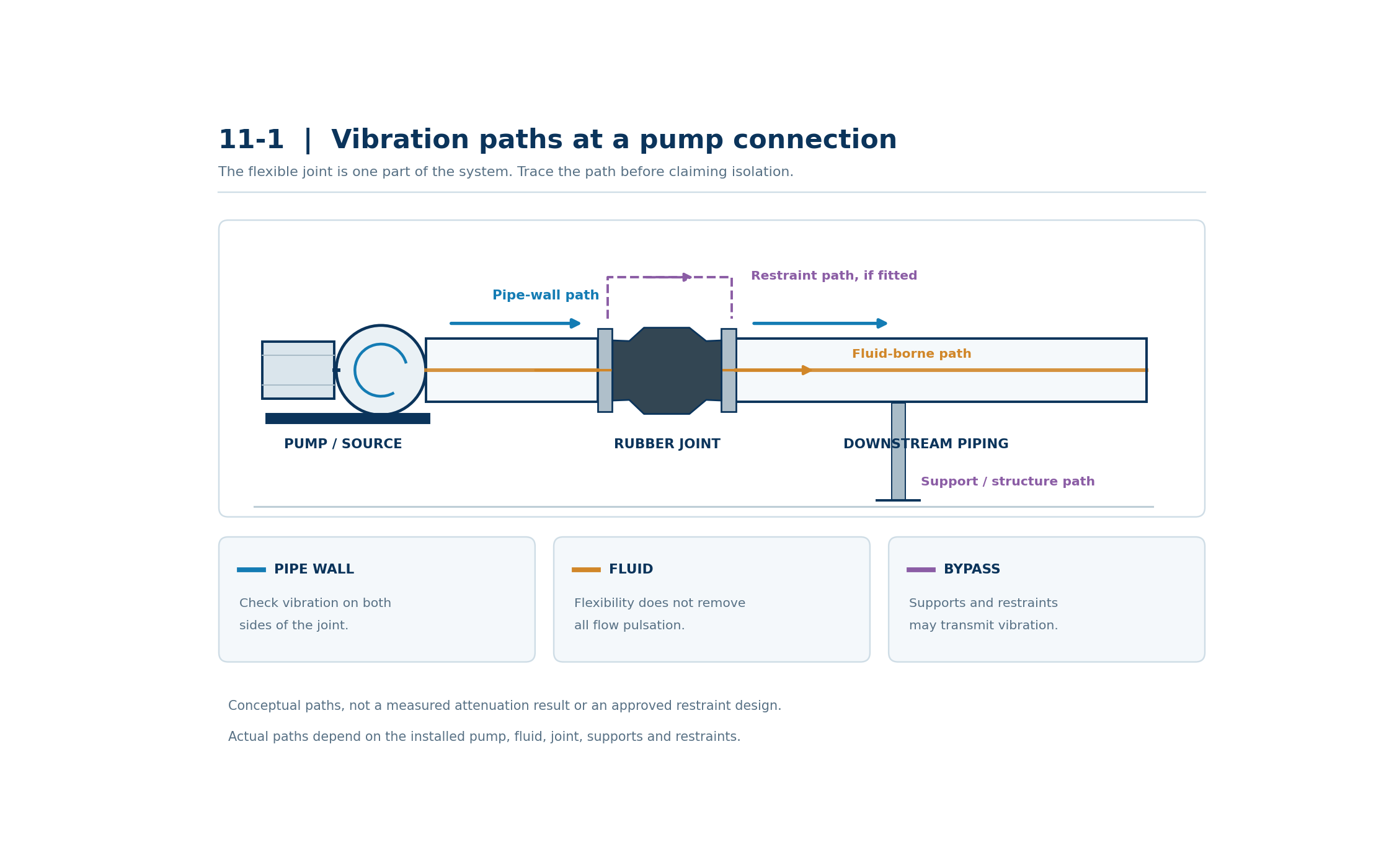
The diagram above identifies possible pipe-wall, fluid-borne and structural or restraint paths. It is a conceptual system sketch, not a measured attenuation result or an approved restraint design.
A flexible rubber joint may help interrupt the pipe-wall path. It cannot be assumed to eliminate fluid-borne pulsation or vibration transmitted through supports. If the main complaint is a tonal noise at a valve, a vibrating pipe support or a noisy room, first establish where the response originates and how it reaches the affected location. A different transmission path may require a change to the pump, flow conditions or support design rather than a different joint alone.
Define what “vibration isolation” means for the project
“Reduces vibration” is incomplete without a location, a quantity and a comparison. A project may be concerned with vibration of the pipe near the pump, motion at a remote support, sound in an occupied room or load transferred to equipment. Those are different outcomes and should not be treated as one performance figure.
Before selecting a test or a product, record:
| Decision | Information to define |
|---|---|
| Source and complaint | Which pump and operating event are involved? Where is vibration or noise observed? |
| Evaluation location | Pump casing, pipe after the joint, support, structure or a defined receiving location |
| Quantity and reporting | Vibration velocity, acceleration or displacement, with unit, RMS or peak convention and frequency range; acoustic measurements separately if noise is the target |
| Operating state | Speed, flow or valve state, suction and discharge pressures, medium, temperature and whether other machines are running |
| Comparison | Agreed baseline, acceptance criterion or both; same sensor positions and comparable states for any before-and-after test |
The quantity and frequency range should be chosen by the project’s vibration specialist for the actual diagnostic or acceptance question. A single overall reading can hide a dominant frequency. Conversely, a spectrum without documented operating conditions may not explain why the response changed.
Measure the system, not just the joint
The measurement plan below suggests P1 on the pump casing and P2 on the downstream pipe; P3 at a support or structure is useful when that path is relevant. These are suggested locations, not a prescribed acceptance test. On a suction-side installation, place the pipe sensor on the corresponding side of that joint. Record the exact position, orientation and mounting method so a later test can repeat them.
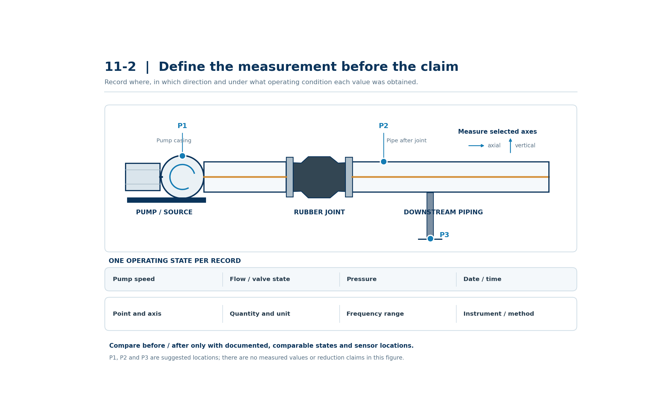
The diagram above shows possible measurement locations and the minimum record needed to interpret a result. It contains no measured values or claimed reduction.
Where practical, record the selected points during the same stable operating state and retain frequency-resolved results. Repeat relevant states, such as the normal duty point and another condition associated with the complaint. Document sensor calibration, measurement bandwidth, averaging, unit and axis. Note pump speed, flow or valve setting, suction and discharge pressures, other operating equipment, and the state of isolators and restraints. For variable-speed pumps, compare the relevant speed ranges instead of relying on one speed.
P1 and P2 are on different components. Subtracting their overall readings or dividing P2 by P1 does not automatically give a rubber joint’s attenuation percentage. Their masses, local resonances and measurement conditions differ. A before-and-after field comparison can describe the installed system’s change only when the test locations, operating states, instruments and surrounding configuration are documented and reasonably comparable. It still cannot assign every change to the joint without examining other changes to the system.
If there is no baseline or agreed acceptance limit, report the measured response and conditions. Do not relabel a single set of readings as a percentage reduction.
What product data should be requested?
Confirm the actual joint model, size, connection, face-to-face length, rubber construction and applicable pressure, temperature, vacuum and movement limits for the proposed assembly. The Mingchao KXT single-sphere rubber expansion joint is one product configuration to review; its published dimensional and movement information is not a measured vibration-isolation rating for every installation.
If a project requires a quantified isolation claim, request any available, configuration-specific dynamic test report or dynamic stiffness data. The report should identify the tested assembly, mounting and restraint arrangement, pressure or preload, temperature, frequency range, excitation and measured quantity. Ask whether those test conditions represent the proposed installation. An unqualified marketing percentage or a result from another size or manufacturer’s product is not a transferable performance guarantee.
The surrounding design needs its own review. Show pump mounts, pipe supports, anchors, guides, tie rods and the joint’s installed position. A restraint needed to manage pressure thrust must not be removed simply to improve a vibration reading. Its load path and contact state can affect isolation, while the safe pressure-thrust design and pump-nozzle loads remain mandatory. See Pressure Thrust and Axial Movement in Rubber Expansion Joints: The Role of Tie Rods and Anchors for that separate design check.
A practical handover for a pump connection review
Send one marked-up piping sketch and the following records:
- Pump type, speed range, normal duty point and the operating state that produces the complaint.
- Suction and discharge connection locations; fluid, temperature and normal, maximum, minimum and test pressures as applicable.
- Joint tag, existing or proposed model, size, flange details, installed length, photographs and available product drawing.
- Required movement and a sketch of pump mounts, nearby pipe supports, anchors, guides and any restraints.
- The precise problem location and available vibration or acoustic data, including sensor positions, axes, units, frequency range and operating conditions.
- The proposed evaluation criterion or a defined, repeatable baseline test. Mark missing information as to be confirmed.
Our pump suction and discharge selection guide covers the wider pressure, movement and installation decisions. Where pump starts, stops or valve events cause a transient pressure concern, use a separate system-level assessment; see Water Hammer and Rubber Expansion Joints: What a Transient Analysis Must Confirm.
Mingchao Fluid Technology can review a drawing-based rubber expansion joint configuration against the supplied operating and connection requirements. A claimed vibration reduction needs a defined measurement basis and applicable evidence for the installed system; product suitability still requires confirmation for the selected assembly. See our rubber expansion joint range and Technical Information & Project Requirements for the next technical review.
Technical references
- ASHRAE Handbook—HVAC Applications, Chapter 49: Noise and Vibration Control, sections on flexible pipe connectors, restraints and resilient supports. General system guidance; it is not a test certificate or rating for a Mingchao joint. handbook.ashrae.org
- ASHRAE Handbook—HVAC Applications, Chapter 38: Testing, Adjusting, and Balancing, section on vibration and noise transmission in piping. General diagnostic guidance; project test procedures and acceptance limits must be specified separately. handbook.ashrae.org
- Fluid Sealing Association, Expansion Joints—Piping Technical Handbook, 8.1 Edition, for expansion-joint selection and installation context. It does not establish an isolation percentage for the proposed installation.