
On this page
- Start with the two pipe ends and the joint end
- HDPE: review the flange adapter and long-term clamping condition
- FRP/GRP: identify the manufacturer’s actual flange and seal
- Follow load and movement into the piping system
- Agree on the assembly and pressure-test boundary
- A joint review sheet that all three parties can use
- Conclusion
- Technical references and related Mingchao articles
A rubber expansion joint can be installed between flanged components in an HDPE or fiberglass-reinforced plastic (FRP/GRP) piping system. The connection should be reviewed as an assembly: the pipe-end adapter, backing ring, sealing interface, expansion-joint end, bolts and surrounding pipe restraints each have a different function. A matching nominal diameter and bolt pattern establish only part of the fit.
This article addresses flanged transitions in a defined piping design, primarily aboveground installations where anchors and guides can be identified. It does not specify a universal HDPE or FRP flange construction. In this article, GRP means glass-reinforced plastic, a commonly used term for fiberglass-reinforced plastic pipe. The selected pipe, flange and joint manufacturers’ approved drawings determine the actual construction.
Start with the two pipe ends and the joint end
Before selecting a rubber expansion joint for HDPE or FRP pipe, obtain a section drawing of each mating pipe end and the proposed joint. Record the exact pipe material and grade, outside diameter, wall or pressure class as applicable, nominal size, flange standard and drilling, face-to-face installation length, and the form of the sealing surface. Identify whether the HDPE pipe uses a fused flange adapter and loose backing ring or another approved connection. Identify whether the FRP/GRP pipe has a fixed flange, a loose-ring stub flange or another manufacturer-specific end.
On the expansion-joint drawing, identify the rubber sealing surface, any bead, the supporting or retaining flange, and how bolt preload is transmitted. These details determine what contacts the pipe flange. The previous Mingchao guide to rubber expansion joint flange connections explains the sealing face and backing support in more detail. The additional question here is whether the particular HDPE or FRP pipe end can mate with that construction without compromising its own sealing and load limits.
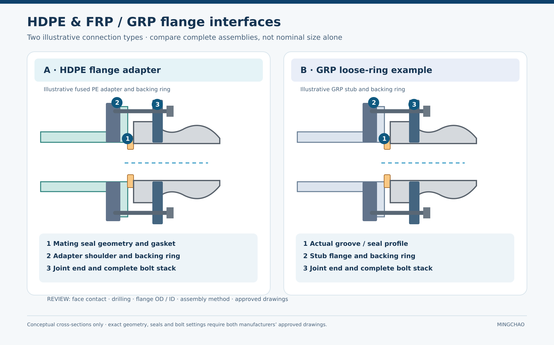
Image caption: Illustrative HDPE flange-adapter and GRP loose-ring interfaces with a rubber expansion-joint end. The indicated seal, backing and bolt-stack positions are review points, not approved dimensions or assembly instructions.
The diagram above compares two possible pipe-end arrangements. It does not establish that either illustrated gasket or flange profile is suitable for a particular Mingchao joint. The three interfaces to approve are the fluid seal between mating faces, the support behind each flange or rubber end, and the complete bolted load path. Check bore clearance, sealing contact width, flange outside diameter, bolt-circle diameter, hole size and count, and bolt length using both component drawings. A shared DN, PN or flange designation does not establish those contact details by itself.
HDPE: review the flange adapter and long-term clamping condition
For a fused HDPE flange adapter, the PE adapter provides the face that mates with the adjoining component, while a backing ring provides support for bolting. The adapter and backing ring must be compatible with each other as well as with the adjoining rubber-joint end. Other PE mechanical adapters have different construction and restraint provisions; do not treat them as equivalent to a fused stub end simply because both present a flange.
The Plastic Pipe Institute’s technical note on PE flanged joints distinguishes PE-to-PE from PE-to-metal contact areas and discusses how viscoelastic stress relaxation of a PE flange adapter can reduce long-term face compression. That is a reason to agree the initial assembly procedure and any later inspection or retightening requirements with the HDPE flange supplier. It is not permission to apply an arbitrary steel-flange torque, add a gasket by default or retighten a rubber expansion joint without consulting its manufacturer.
In particular, determine whether the rubber joint’s own end already forms the intended seal. If an additional gasket is proposed, its location, material, thickness and compatibility must be approved for both mating faces. A gasket recommended for one PE-to-metal flange combination is not automatically suitable when the other side is a rubber expansion-joint flange. Check that the chosen backing ring and bolt stack distribute clamping force as required by both suppliers.
Also identify who has designed the PE pipe’s connection against axial pullout and other forces. A flange adapter is a connection detail; it does not, on its own, prove that the whole pipe system has adequate anchors or that equipment nozzles have acceptable loads.
FRP/GRP: identify the manufacturer’s actual flange and seal
Request a section of the actual FRP flange, including any seal groove, stub flange and backing ring. Confirm whether the specified seal requires a groove, a flat face or another defined geometry. Then examine the proposed rubber-joint face: two faces may have compatible drilling and still present incompatible sealing features. Ask both manufacturers to approve the gasket or sealing arrangement, bolt sequence, washers and allowable tightening procedure for the combined connection. Do not publish a single torque value for “FRP flanges”; it depends on the exact flange construction and seal.
The FRP pipe supplier must also confirm how the flange and nearby pipe are supported, what loads the pipe end can carry, and whether installation or test conditions differ from normal operation. A rigidly connected support, a guide that permits axial sliding, and a pipe cradle are not interchangeable simply because each touches the pipe.
Follow load and movement into the piping system
The rubber body may accommodate specified motion, but the connected HDPE or FRP pipe and flange still see forces and moments. Establish the pressure cases at the joint, including test and transient cases, and identify where pressure thrust is reacted. Separately record the movement expected at the joint and the movement allowed by each pipe-end connection and restraint arrangement.
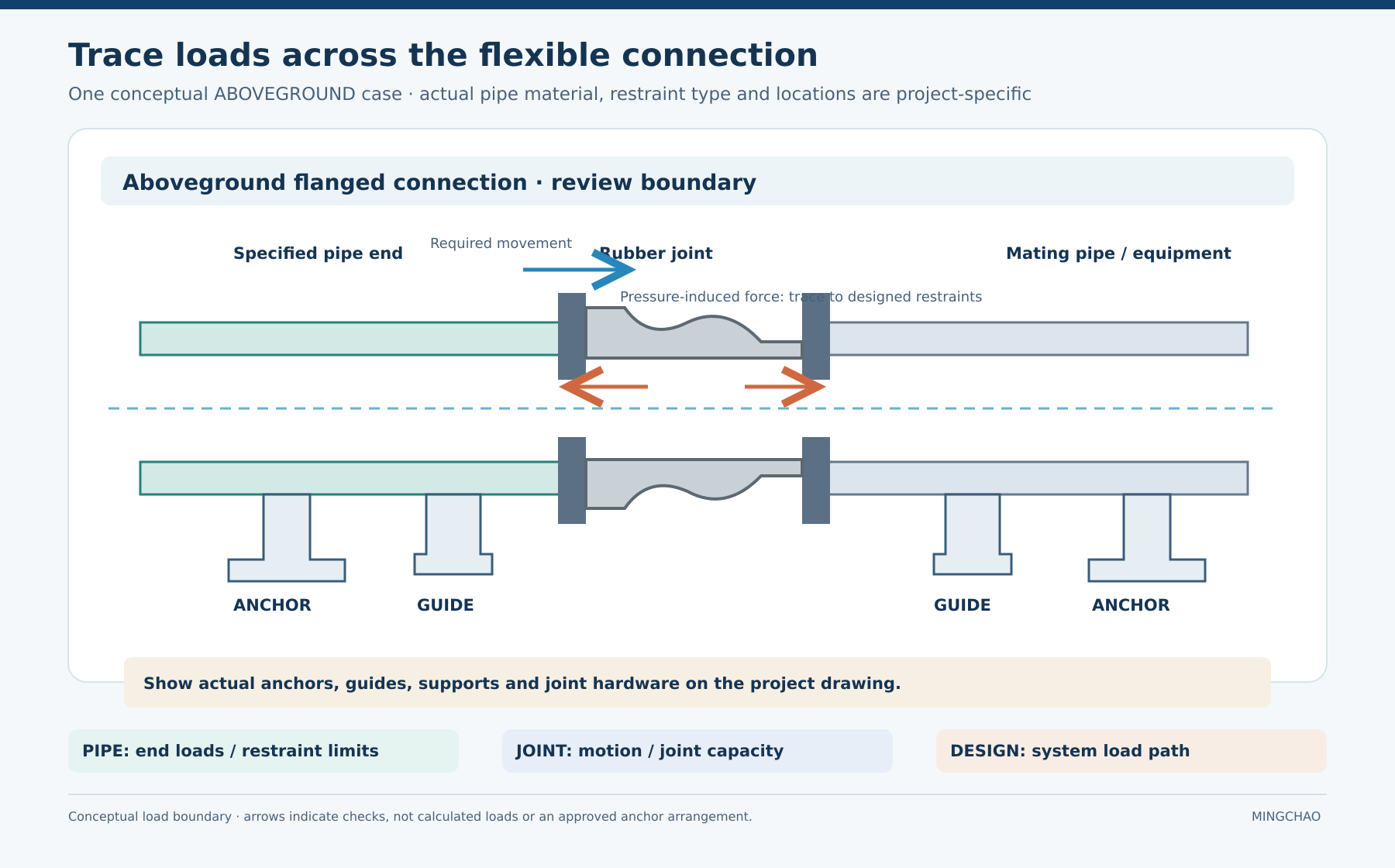
Image caption: Conceptual aboveground load boundary around a flanged rubber expansion joint. The arrows identify movement and force-path questions; anchor and guide locations must come from the project piping design.
The diagram above shows the questions the piping engineer needs to resolve. Which components react the pressure-induced axial force? Which supports carry pipe and fluid weight? Can the guides accommodate the pipe’s intended longitudinal movement? What forces and moments reach nearby equipment? A flexible joint by itself cannot establish those answers, and the illustration is not an approved anchor-spacing or support-detail drawing.
Our article on pressure thrust, tie rods and anchors explains the alternative thrust paths. The article on combined movement explains why installation offset and operating displacement must be checked together. For this mixed-material connection, those system-level checks must also be compared against the pipe-end and backing-ring limits supplied for the actual HDPE or FRP components.
Do not assume that every FRP or HDPE installation needs the anchor layout shown above. Buried pipe, non-restrained couplings, restrained joints and aboveground supports have different boundaries. This figure illustrates one aboveground review case only. The applicable pipe supplier’s installation guide and the project’s piping design govern the actual arrangement.
Agree on the assembly and pressure-test boundary
The project installation instruction should identify a single approved sequence for aligning the two pipe ends, fitting any approved gasket, tightening bolts and inspecting the completed joint. Neither HDPE nor FRP pipework should be pulled into alignment by tightening the expansion-joint bolts. The piping design must support the connected pipe independently; the rubber joint should not carry unsupported pipe weight.
Pressure testing is another defined load case, not simply a repeat of normal operation. Record test pressure and duration at the joint, the test medium, temporary restraints if any, and which components remain in the test boundary. Ask the pipe supplier and joint supplier to confirm their respective limits and ask the piping engineer to approve the load path. If their assembly instructions disagree, resolve the difference on the approved project drawing before installation.
A joint review sheet that all three parties can use
| Review item | Pipe or flange supplier confirms | Rubber-joint supplier confirms | Piping designer confirms |
|---|---|---|---|
| Actual end construction | HDPE adapter or FRP flange section; backing ring; dimensional tolerances | Joint end, rubber seal and supporting flange | The specified pipe ends and joint match the layout |
| Sealing and bolting | Face geometry, gasket requirements and allowable assembly procedure | Compatibility of the proposed mating face, gasket and bolt stack | One agreed assembly method is issued for the interface |
| Pressure and temperature | Pipe-end and flange limits for each case | Complete joint limits for each case | Operating, transient and test cases at this location |
| Movement | Allowed movement and loading at the pipe end | Axial, lateral and angular capability of the selected joint | Installed position, simultaneous motions and support layout |
| Force path | Permitted pipe-end loads and restraint details | Intended role and capacity of any joint restraint hardware | Anchors, guides, equipment loads and test restraints |
| Verification | Approved pipe-end drawing and instructions | Approved joint drawing and instructions | Coordinated connection detail and installation sign-off |
An empty cell is a request for information, not a reason to borrow a value from another manufacturer’s catalogue. If a proposed connection requires a different adapter, backing ring, gasket or joint end, update the drawing and repeat the interface check.
Conclusion
An HDPE or FRP/GRP pipeline can be connected to a suitable rubber expansion joint when the complete interface and restraint boundary are engineered together. Begin with the actual pipe-end and joint-end drawings. Approve the sealing contact and backing support, then check bolting, long-term assembly conditions, expected movement and pressure-test loads. The pipe supplier, joint supplier and piping designer each supply different parts of that answer.
Technical references and related Mingchao articles
Primary technical references
- Plastic Pipe Institute — PE Flanged Joints (TN-38, PDF): PE adapter and flange-assembly considerations. Its examples and procedures apply within the document’s stated scope.
- Plastic Pipe Institute — Flange Adapters: distinction between fused and mechanical PE adapter constructions.
- Fluid Sealing Association — Expansion Joints: Piping Technical Handbook: general non-metallic expansion-joint selection and installation reference.
Related Mingchao reading
- Rubber Expansion Joint Flange Connections: Sealing Faces, Backing Support and Bolt Assembly
- Pressure Thrust and Axial Movement in Rubber Expansion Joints: The Role of Tie Rods and Anchors
- Combined Movement in Rubber Expansion Joints: Installation Offset and Operating Displacement
- Technical Information & Project Requirements
Mingchao Fluid Technology can review the proposed rubber-joint construction against the pipe-end drawings and service conditions. The final interface and pipe-restraint design should be approved by the responsible project engineers. Visit the Mingchao Fluid Technology website for product information and technical enquiries.