
On this page
- 1. Calculate Velocity from Actual Flow and Clear Bore
- A short calculation example
- 2. Distinguish Flow-Induced Vibration from Equipment Vibration
- 3. Check the Installed Arrangement Against Applicable Guidance
- 4. Compare the Design Options
- 5. Specify the Liner as Part of the Assembly
- 6. Provide a Complete Flow Review
- Technical References and Related Resources
A corrugated metal hose can meet its pressure rating and still be unsuitable for the flow passing through it. Flow suitability depends on actual velocity, the internal passage, installed geometry and operating conditions.
The practical decision is whether the proposed assembly needs a larger clear bore, revised routing or an engineered flow liner. That decision requires more than a nominal pipe size or a catalogue pressure value.
This guide addresses single-phase flow in industrial corrugated metal hose assemblies. Two-phase flow, flashing, condensation and significant gas expansion require additional process assessment.
1. Calculate Velocity from Actual Flow and Clear Bore
For a circular passage, mean velocity is:\[ v=\frac{Q_{\mathrm{actual}}}{A}, \qquad A=\frac{\pi D^{2}}{4} \]
Here, \(Q_{\mathrm{actual}}\) is the volumetric flow at the local operating conditions, and \(D\) is the relevant clear internal diameter.
Use consistent units: m³/s and m² give velocity in m/s.
Nominal diameter is not a substitute for verified clear bore. Check the hose, liner, fittings and reducers. Different sections may have different flow areas and local velocities.
For gases, a flow stated in Nm³/h or Sm³/h must include its reference pressure and temperature. Convert it to actual volumetric flow using the operating conditions and an appropriate gas-property method. Where pressure or temperature changes substantially along the assembly, one inlet calculation may not represent the entire passage.
A short calculation example
At an actual flow of 10 m³/h:
| Circular clear bore | Mean velocity |
|---|---|
| 50 mm | 1.41 m/s |
| 40 mm | 2.21 m/s |
Reducing diameter by 20% increases mean velocity by approximately 56% at the same actual flow.
These are illustrative dimensions, not product ratings. The example explains why a liner’s clear bore must be included in the calculation.
2. Distinguish Flow-Induced Vibration from Equipment Vibration
A vibrating hose does not necessarily have a single excitation source.
| Possible source | Useful evidence |
|---|---|
| Equipment mechanical vibration | Equipment speed, vibration measurements and transmission path |
| Pressure pulsation | Pressure variation, frequency and operating sequence |
| Flow-induced excitation | Actual velocity, fluid properties, passage geometry and changes with flow |
These mechanisms can coexist. Noise or a crack photograph alone does not establish the cause.
Flow interacting with corrugations can excite vibration; under certain conditions, resonance can cause rapid assembly failure. A flow liner can reduce direct interaction between the conveyed medium and the corrugated passage. It does not establish that all vibration has been eliminated.
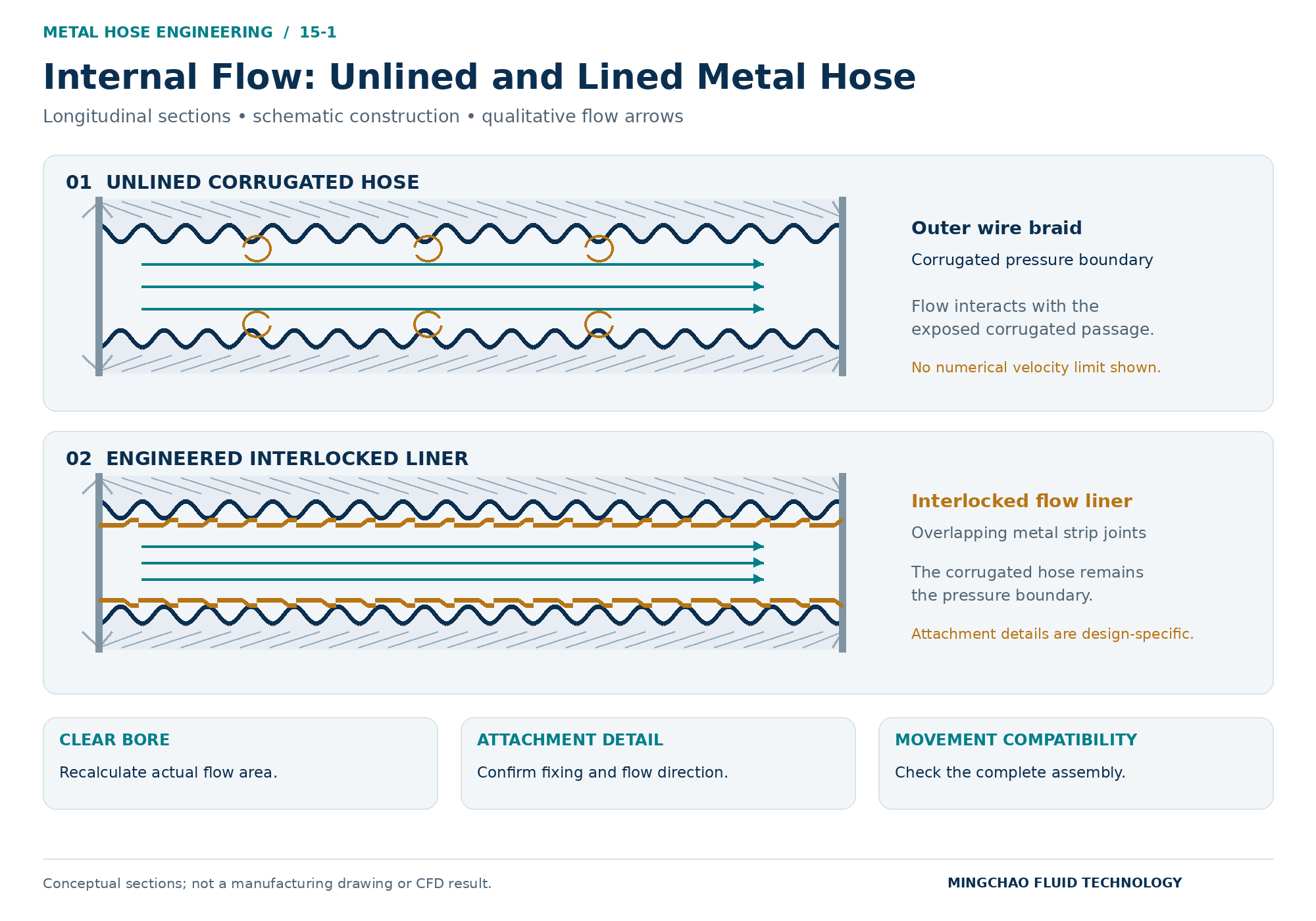
The illustration above compares exposed corrugations with an interlocked flow liner. Arrows are qualitative, not calculated flow trajectories. The corrugated hose remains the pressure boundary; liner construction and attachment are design-specific.
3. Check the Installed Arrangement Against Applicable Guidance
A velocity recommendation is meaningful only within its stated scope.
Check whether the source applies to the fluid, hose construction and installed configuration. Hose Master’s published guidance, for example, distinguishes straight and bent arrangements, braided and unbraided hose, and gas and liquid service.
Do not apply a straight-run recommendation automatically to a tightly curved installation. Equally, satisfying minimum bend radius does not complete the flow review.
Record the inlet arrangement, reducers, bends, operating positions and any changes during movement. If the proposed duty falls outside the available guidance, obtain an application-specific assessment rather than choosing a convenient limit from another product.
A velocity calculator establishes mean velocity. It does not predict resonance, pressure loss or fatigue life.
4. Compare the Design Options
| Option | Intended benefit | Checks required after the change |
|---|---|---|
| Larger clear bore | Lower mean velocity at the same actual flow | Reducers, space, pressure capability, bend radius, weight and equipment loads |
| Revised routing | Address configuration-dependent flow concerns | Applicable guidance, inlet conditions, clearance, supports and movement |
| Engineered flow liner | Reduce direct flow interaction with corrugations | Liner bore, attachments, pressure drop, material compatibility and movement limits |
Increasing hose diameter may help, but retained small-bore fittings still require local velocity and pressure-loss checks.
A liner occupies space inside the hose. Although it changes the surface exposed to flow, the resulting pressure drop cannot be assumed to decrease: bore, liner construction, length, fittings and operating conditions all matter.
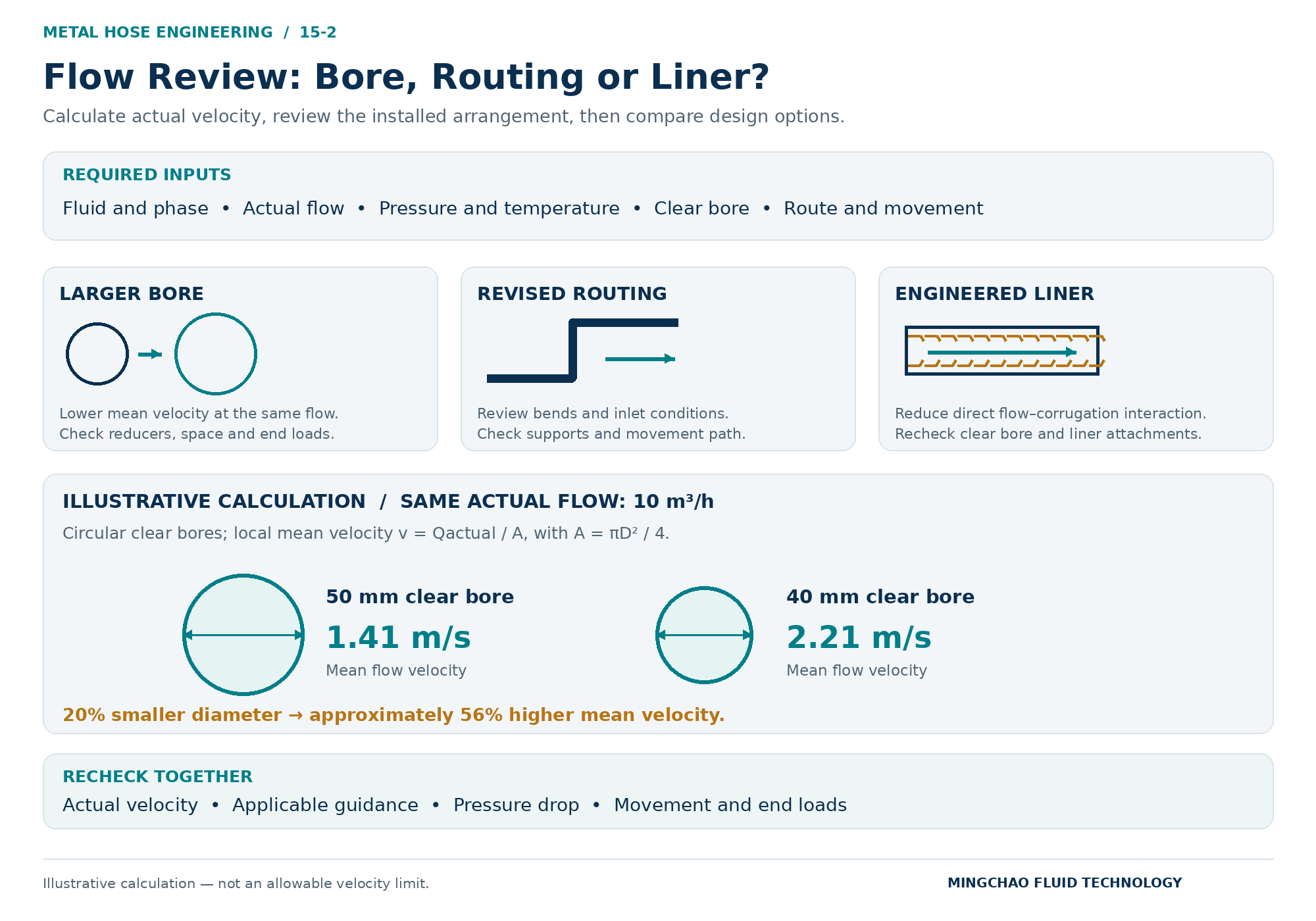
The illustration above connects the required inputs to the design options. Its calculation compares circular clear bores at equal actual flow; neither velocity is presented as an allowable limit.
5. Specify the Liner as Part of the Assembly
“Metal hose with liner” is an incomplete specification.
An interlocked metal liner consists of formed, mechanically interlocked strip. It is not equivalent to a seamless smooth tube and should not be treated as an independent pressure-tight barrier.
Confirm:
- Liner type, material and clear bore.
- Attachment details and permitted flow direction.
- Compatibility with installation and operating movement.
- Minimum bend radius for the complete lined assembly.
- Temperature, corrosion, abrasion and inspection requirements.
Penflex’s guidance discusses liner attachment and extension state as design considerations, particularly for long assemblies. These details cannot be resolved by simply inserting an unspecified liner into an existing hose.
Do not assume a liner increases working pressure or creates a universal allowable-velocity multiplier. Confirm the finished assembly’s limits separately.
6. Provide a Complete Flow Review
A useful review package contains:
| Input | Required detail |
|---|---|
| Fluid | Composition, phase and relevant solids or contamination |
| Flow | Normal and maximum flow; actual or reference conditions |
| Operating conditions | Corresponding pressure and temperature; pressure basis |
| Passage | Hose, liner, fitting and reducer clear bores |
| Installation | Length, bends, supports and operating movement |
| Acceptance requirements | Applicable velocity guidance, pressure-drop allowance and required verification |
Where unexplained noise or vibration is present, add measured operating data and its relationship to flow and equipment speed. More detailed analysis or testing should answer a defined question; a decorative flow simulation is not evidence of acceptable service life.
For a Mingchao JR Stainless Steel Flexible Metal Hose enquiry, submit the flow conditions and installation drawing together. Liner availability and construction require project-specific confirmation.
Any change to bore, routing or liner should also trigger a renewed geometry and equipment-load review.
Technical References and Related Resources
Mingchao resources
- JR Stainless Steel Flexible Metal Hose
- Live Length, Bend Radius and Installation Movement
- Technical Information & Engineering Resources
External technical references
- Hose Master — Velocity in Metal Hose
- Hose Master — Select the Right Corrugated Metal Hose
- Penflex — Managing High Flow Velocity with Interlocked Liners
External recommendations must be checked for applicability. They are not Mingchao product ratings.
Mingchao Fluid Technology
www.mingchaoft.com