
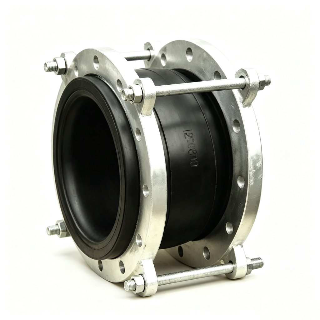
Rubber Expansion Joints
Restrained Rubber Expansion Joint with Tie Rods
The Mingchao Restrained Rubber Expansion Joint with Tie Rods combines a flexible flanged rubber body with external restraint hardware. It is used where the piping design requires axial extension or pressure-thrust movement to be controlled while retaining movement capability according to the selected joint and restraint configuration.
RUBBER EXPANSION JOINTS · RESTRAINED / CONTROL ROD CONFIGURATION — also specified as a rubber expansion joint with control rods, tie rods or limit rods; rubber flexible joint with control rods; or control unit rubber expansion joint.
- Product Type
- Restrained Rubber Expansion Joint
- Restraint Configuration
- Limit Rod / Tie Rod / Project-Specific Control Rod Arrangement
- Common Size Reference
- DN25–DN300
- Larger Sizes
- Custom to confirmed project requirement / approved drawing
- Working Pressure
- PN10 / PN16 common reference; final rating confirmed for selected configuration
- Movement
- Axial / Lateral / Angular within selected restraint setting
- Rubber Options
- EPDM / NBR / NR / CR / other compatible compounds to service requirement
- Flange Standards
- GB / DIN / EN / ASME-ANSI / JIS / BS
- Reference Standard
- GB/T 26121-2010
- Production
- Standard configurations + custom production to approved drawing
ProductionStandard configurations + custom production to approved drawing
Project Configuration
Mingchao can customize the product configuration based on the technical information, operating conditions and dimensional data you provide. Final configuration can be reviewed and manufactured to the approved project drawing.
Restrained Rubber Expansion Joint Overview
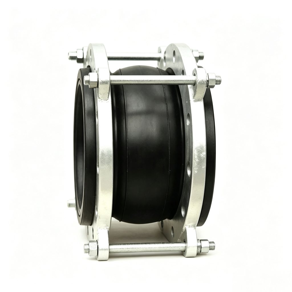
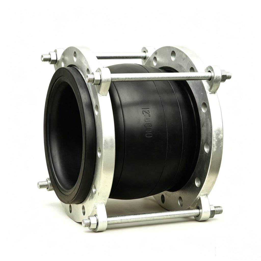
Unlike an unrestrained rubber expansion joint, the restrained configuration adds external rods, plates, nuts and related hardware across the flange connection. The restraint arrangement is selected together with the nominal size, working pressure, required movement, flange interface and piping support conditions.
The rubber body continues to provide vibration isolation and flexible movement accommodation, while the external hardware controls the allowable movement or axial restraint according to the approved configuration.
The restraint system must be selected as part of the complete piping design. One rod quantity, plate geometry or nut setting must not be presented as universal for every size or operating condition.
Control Rods, Limit Rods & Tie Rods
A control unit or control rod arrangement is the general external restraint hardware connecting the two flange sides of a restrained rubber expansion joint. The selected assembly works with the rubber body and the piping restraint design; it is not a universal accessory setting.
Limit Rod Configuration
A preset gap may allow defined normal movement. The limit rods engage at the selected limit to prevent excessive extension or compression according to the engineered arrangement.
Tie Rod Configuration
Tie rods are used when continuous axial restraint is required. They restrain the joint axially and therefore influence the remaining allowable movement.
Limit rods and tie rods are not mechanically identical. Final rod quantity, diameter, plate geometry, washers, nuts and gap setting must be confirmed by DN, working pressure and thrust, movement requirement, piping anchors and guides, and the approved drawing.
Engineering note: Do not change the rod quantity, rod diameter, plate geometry or nut/gap setting in the field without engineering confirmation.
Construction & Available Materials
Available materials are selected for the actual medium, operating condition, flange interface, environment and approved restraint configuration.
| Component | Available / Reference Configuration |
|---|---|
| Rubber Body | EPDM / NBR / NR / CR / other compatible compound according to medium and operating condition |
| Flanges | Carbon steel / galvanized steel / stainless steel / project-specific |
| Control / Limit / Tie Rod Hardware | External rods, plates, nuts and project-specific restraint arrangement |
| Flange Interface | GB / DIN / EN / ASME-ANSI / JIS / BS drilling or approved drawing |
Technical & Configuration Data
Configuration values below are project-selection references. DN-by-DN movement and dimensional values must be confirmed for the selected restrained-joint configuration.
| Parameter | Reference / Available Configuration |
|---|---|
| Configuration | Single- or double-sphere rubber body with external restraint hardware to project requirement |
| Common Size Reference | DN25–DN300 |
| Larger / Non-Standard | Custom dimensions to confirmed requirement and approved drawing |
| Working Pressure | PN10 / PN16 common reference; final rating confirmed for selected configuration |
| Rubber | EPDM / NBR / NR / CR / other compatible compounds |
| Flange Standards | GB / DIN / EN / ASME-ANSI / JIS / BS |
| Flange Options | Carbon steel / galvanized steel / stainless steel / project-specific |
| Movement | Axial / lateral / angular within selected restraint setting and piping design |
| Face-to-Face | Standard or custom length to approved drawing |
Confirm final size, working pressure, movement, material, face-to-face length and restraint setting against the approved drawing and complete piping design.
How to Select a Restrained Rubber Expansion Joint
Provide the following project data so the rubber body, flange interface and restraint function can be reviewed together.
| Selection Item | Information to Provide | Review Note |
|---|---|---|
| Nominal Size | DN / NPS | Common reference + custom size |
| Rubber Body | Single / Double Sphere / Approved Special Form | Confirm complete body configuration |
| Working Pressure | PN / Class / Actual Working Pressure | Confirm pressure and thrust basis |
| Medium / Fluid | Water / wastewater / air / oil / chemical / other | Final rubber selected to actual service |
| Operating Temperature | Minimum / normal / maximum | Final material and pressure rating confirmed for service condition |
| Face-to-Face Length | Required L | Standard or approved custom length |
| Movement Requirement | Axial / lateral / angular | State direction and required movement |
| Flange Standard | GB / DIN / EN / ASME-ANSI / JIS / BS | Confirm drilling and mating interface |
| Restraint Function | Movement limit / continuous axial restraint | Distinguishes limit-rod and tie-rod duty |
| Rod & Plate Design | Quantity / rod size / plate geometry / gap setting | Confirmed by project engineering / approved drawing |
| Materials / Coating | Flange / rods / plates / nuts / finish | Confirm environment and project requirement |
| Drawing & Quantity | CAD / sketch / sample / quantity | Provide available reference files |
Typical Applications
Pump & Equipment Connections
Flexible flanged connections where the piping design requires excessive joint extension to be controlled.
HVAC & Chilled-Water Piping
Vibration isolation and controlled movement in reviewed building-services piping.
District Cooling Piping
Flexible connections selected with the system restraint and support arrangement.
Water Supply Systems
Restrained rubber-joint configurations for reviewed water piping layouts.
Wastewater Treatment
Equipment and process-water connections subject to medium and material review.
Cooling-Water Circulation
Pump, equipment and pipeline connections with project-specific restraint settings.
Industrial Piping
Systems requiring a flanged rubber expansion joint with tie rods, limit rods or control rods.
Movement-Controlled Installations
Locations where excessive extension must be controlled or restraint is required by piping design.
Final suitability depends on the selected configuration, actual operating conditions, restraint design, anchors, guides and supports.
Anchors, Guides & Pressure Thrust
Control rods do not eliminate the need to review the complete piping system. Selection must consider anchors, guides, equipment nozzle loads, internal-pressure thrust, required movement, piping alignment and support conditions.
The restraint configuration and the piping restraint scheme must be evaluated together. A tie-rod arrangement must not be treated as automatically replacing every anchor or guide.
Installation Guidelines
Use the approved project drawing and confirmed restraint setting during installation and commissioning.
1. Align Piping
Align piping before installation.
2. Neutral Position
Install the rubber joint in its intended neutral position unless the approved drawing specifies otherwise.
3. Do Not Pull Misalignment
Do not use control rods to pull severely misaligned piping into position.
4. Tighten Evenly
Tighten flange fasteners evenly and progressively.
5. Verify Piping Restraint
Verify anchors, guides and supports before pressurization.
6. Confirm Rod Setting
Confirm the restraint rod setting against the approved project drawing.
7. No Unreviewed Changes
Do not change rod quantity, rod diameter, plate geometry or nut/gap setting without engineering review.
8. Initial Inspection
Inspect the joint after initial pressurization for unexpected elongation, compression or misalignment.
Custom Restrained Rubber Expansion Joint Configurations
Mingchao can review non-standard DN, face-to-face length, single- or double-sphere body, rubber compound, flange drilling, flange material, control / limit / tie rod arrangement, rod and plate configuration, corrosion-protection requirement, and a project or customer drawing.
Final dimensions and restraint configuration are confirmed against the approved project drawing and operating conditions.
restrained rubber expansion joint Product Photograph & Control Rod Drawing
Technical Datasheet
Product configuration, catalog drawing and project-specific dimensional information can be reviewed with the quotation.
Information Required for Quotation
Send the available project information for technical review and quotation.
- DN / NPS
- Single or double sphere
- Flange standard / pressure class
- Working pressure
- Medium
- Operating temperature
- Face-to-face length
- Required axial / lateral / angular movement
- Limit rod or tie rod requirement
- Piping anchoring / support information if available
- Flange material
- Rubber material if specified
- Quantity
- Project drawing / CAD / sketch if available
Technical Datasheet
Restrained Rubber Expansion Joint with Tie Rods
Technical Datasheet · PDF