On this page
- 1. Locate the Leak Before Assigning a Cause
- 2. Preserve the Installed Geometry
- 3. Treat Damage Patterns as Questions to Investigate
- 4. Reconstruct the Service History
- 5. Retain the Failed Assembly and Its Identity
- 6. Specify the Replacement Against the Findings
- Related Products and Technical Resources
- Technical References
Replacing a leaking metal hose with an identical assembly may leave the original problem unresolved. Before specifying a replacement, establish where the leak originated, how the hose was installed and what happened during service.
A useful metal hose failure investigation separates observations, possible explanations and verified findings. A crack, damaged braid or wet connection provides evidence, but does not establish the cause by itself.
This guide covers braided corrugated metal hose assemblies. Inspection, removal and sample handling must follow the site’s isolation, depressurization, cooling and decontamination procedures. Do not approach a suspected pressurized leak to locate it by hand.
1. Locate the Leak Before Assigning a Cause
Record the first reported location of visible liquid and distinguish it from the confirmed leakage source. Liquid can travel along the assembly before collecting or dripping elsewhere.
Investigate these areas separately:
- Connection and sealing interface: the joint between mating components.
- End-connection region: the transition between the hose and its end fitting, including applicable welds.
- Corrugated hose: the flexible pressure-containing tube beneath the braid.
- External braid and contact areas: locations showing rubbing, broken wires or other damage.
In a conventional braided corrugated metal hose, the corrugated tube contains the fluid. The external braid reinforces the assembly; it is not a separate fluid-tight barrier.
Photograph the complete installation and progressively closer views. Include a scale where practical and identify each end consistently, such as End A and End B.
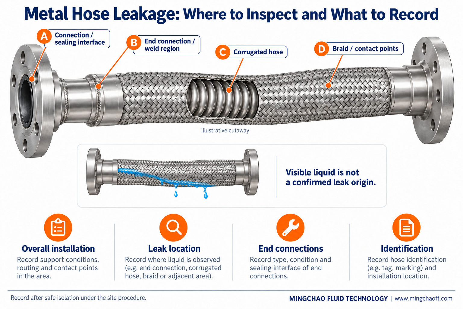
The illustration above separates inspection areas and the information to record. It does not represent a confirmed failure or a universal end-connection design.
2. Preserve the Installed Geometry
A removed hose no longer shows its original routing, restraint or relationship to nearby equipment. Where safe access is permitted, record these conditions before disconnecting it:
| Installation detail | What to record |
|---|---|
| Assembly identity | Tag, drawing revision, nominal size, materials and installation date |
| Length and routing | Overall length, effective flexible length and installed shape |
| Bending | Local bend locations, measuring method and proximity to the ends |
| Orientation | End-fitting alignment, bending plane and possible twisting |
| Surroundings | Supports, contact points, abrasion marks and nearby equipment |
| Movement | Cold, operating and extreme positions, where reliable records exist |
A bend-radius measurement alone does not establish suitability. Compare the installed condition with the applicable assembly requirements, including whether the hose experiences fixed bending or repeated movement.
For the distinction between overall length and the working flexible section, see Stainless Steel Flexible Metal Hose: Live Length, Bend Radius and Installation Movement.
3. Treat Damage Patterns as Questions to Investigate
Describe what is visible before naming the failure mechanism. Record the location, extent and orientation of damage rather than writing only “fatigue failure” or “corrosion.”
| Observation | Evidence to collect | Question requiring verification |
|---|---|---|
| Crack near an end | Routing, movement direction, vibration history and end restraint | Did repeated local bending, torsion or another load contribute? |
| Worn or broken braid wires | Contact marks, support arrangement and handling records | Was external contact or another damage mechanism involved? |
| Hole, thinning or corrosion signs | Material records, internal medium and external exposure | What damage mechanism affected which surface? |
| Liquid near a connection | Sealing interface, weld region and liquid tracking path | Which component or interface actually leaked? |
Different mechanisms can produce similar signs. Penflex’s investigation guidance, for example, notes that cracking and braid wear are not exclusive indicators of vibration fatigue. They require interpretation alongside other evidence. Penflex
Staining alone does not prove through-wall corrosion, and a leak near a weld does not by itself prove defective welding. Further examination may be necessary.
4. Reconstruct the Service History
The relevant conditions are those experienced before leakage—not only the readings available after shutdown.
Build a short timeline covering:
- Installation, commissioning and first reported leakage.
- Normal pressure and temperature, plus recorded excursions.
- Startups, shutdowns, valve events and changes in operating mode.
- Repeated movement and equipment vibration.
- Medium composition, concentration and cleaning conditions.
- Maintenance, relocation or changes to supports and connected equipment.
Identify missing information as unknown. Do not replace an unavailable pressure history with a nominal system rating.
Where vibration is suspected, record the measurement location, direction, operating state and available measurement settings. A statement such as “the pump vibrates heavily” is insufficient to establish the loading experienced by the hose.
Assembly pressure capability must also be checked against the actual temperature, braid and end connections. See Metal Hose Pressure Ratings: Temperature, Braid and End-Connection Limits.
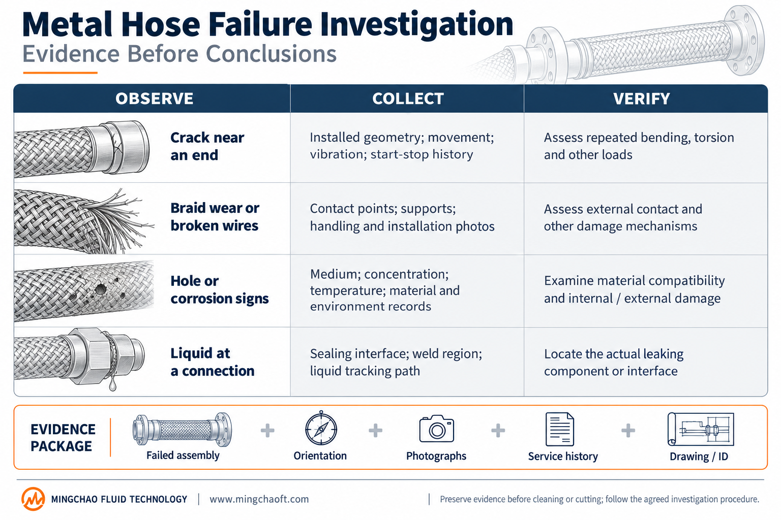
The matrix above connects visible observations with supporting records and verification questions. It is an investigation aid, not an automatic diagnosis.
5. Retain the Failed Assembly and Its Identity
Agree sample handling with the responsible investigator before cleaning, cutting or separating components. Site safety and contamination controls take priority.
Where permitted:
- Preserve the assembly’s identification and mark its installed orientation without marking suspected fracture surfaces.
- Record anything changed during removal.
- Protect damaged surfaces from rubbing and further distortion.
- Retain associated seals or mating parts when requested.
- Document any required cleaning or decontamination.
Do not bend a damaged hose merely to make the defect more visible. Cutting through the suspected origin or aggressive cleaning can remove useful evidence.
Examination methods should follow the investigation question. Visual inspection, leak testing, material identification and fracture examination provide different information; none should be treated as a universal answer.
6. Specify the Replacement Against the Findings
Replacing the same size and length does not demonstrate that the replacement addresses the failure.
Before release, prepare a concise handover record:
| Item | Required information |
|---|---|
| Confirmed findings | Evidence supporting each conclusion and unresolved questions |
| Replacement configuration | Size, materials, braid, end connections and approved drawing |
| Installation | Routing, flexible length, movement and support requirements |
| Service conditions | Pressure, temperature, medium and relevant operating events |
| Acceptance | Required inspections, tests, records and responsible parties |
If the cause remains unresolved, state that limitation. Proposed changes to alloy, length, braid, routing or supports require review; they are not interchangeable remedies.
Mingchao can review drawings and operating requirements for a proposed replacement assembly. Provide installation photographs, assembly identification, service history and available investigation findings. Final selection should address both the assembly and its installed conditions.
Related Products and Technical Resources
- JR Stainless Steel Flexible Metal Hose — product construction, dimensional information and the corresponding datasheet download.
- Flexible Metal Hose Assemblies — assembly configuration enquiries.
- Flexible Metal Hose at Equipment Connections: Bending Stiffness and End Loads — related equipment-loading considerations.
- Technical Information & Project Requirements — information for technical review.
Technical References
- Penflex — Basic Steps in Hose Assembly Failure Analysis
- Penflex — Failure Analysis: Braided Hose in High Vibration Applications
External references support investigation principles. Their product ratings, examples and findings do not establish the cause of a particular failure or the performance of a Mingchao assembly.
Mingchao Fluid Technology
www.mingchaoft.com