On this page
- 1. Bend Radius and Bending Force Answer Different Questions
- 2. Request Reaction Data for the Installed Configuration
- 3. Treat Pressure Restraint and Equipment Loads Separately
- 4. Assess the Hose Within the Piping System
- 5. Compare Loads at the Same Point and Operating Condition
- 6. Use a Defined Data Handover
- Project Information for Mingchao Review
- Technical References and Related Resources
A flexible metal hose can accommodate movement and still impose unacceptable forces or moments on connected equipment. Meeting the pressure rating and minimum bend radius does not, by itself, establish acceptable pump nozzle loads.
The assessment needs three inputs: the hose assembly’s reaction data, the installed piping arrangement and the equipment’s allowable loads. These must refer to compatible operating conditions.
This guide covers braided corrugated metal hose assemblies at equipment connections.
1. Bend Radius and Bending Force Answer Different Questions
Minimum bend radius describes a geometrical limit under specified conditions. It does not state the force required to bend the hose or the moment transmitted to its fittings.
Hose flexibility can mean tight bending capability, resistance to repeated flexing or low resistance to displacement. These properties are related but are not interchangeable. Hose Master makes this distinction in its discussion of corrugated hose selection. hosemaster.com
For an equipment connection, ask:
What forces and moments does this assembly transmit when installed and moved through the required operating positions?
A hose that bends easily by hand while unpressurized does not answer that question for operating service.
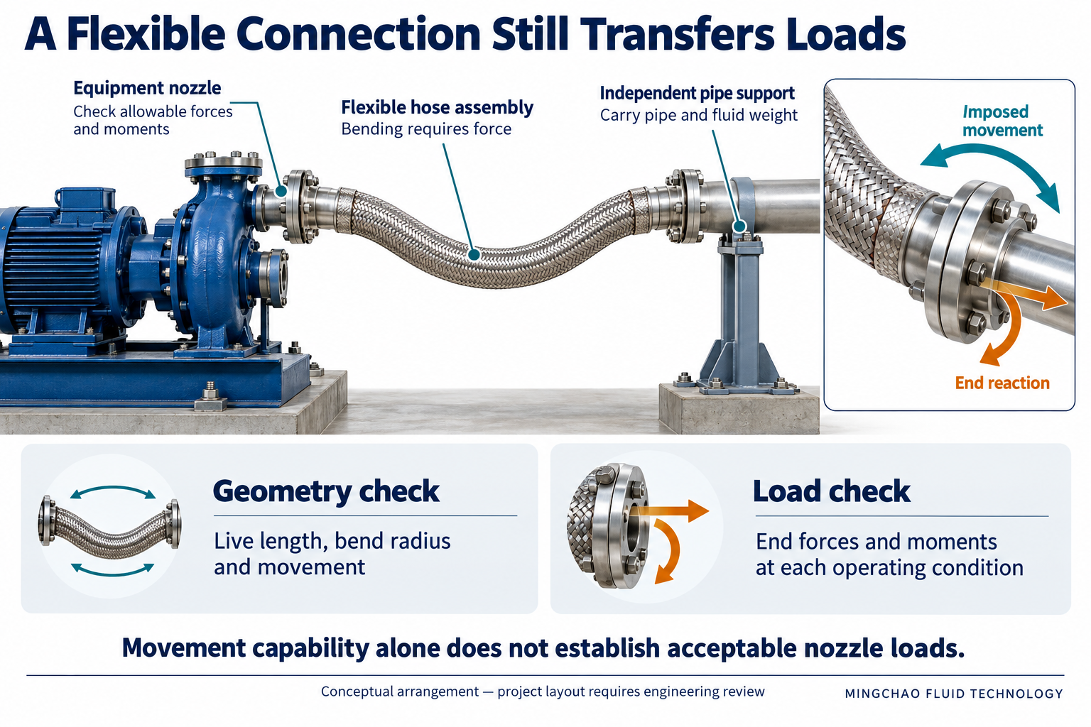
The illustration above separates movement accommodation from equipment-load assessment. The arrangement and arrows are conceptual; they do not specify an approved hose route, bend radius or calculated reaction.
2. Request Reaction Data for the Installed Configuration
A useful force–displacement curve or stiffness value must identify its conditions. Request:
- Assembly size, materials, braid construction and drawing revision.
- Live length, initial shape and end-fitting orientation.
- Pressure, temperature and imposed translations or rotations.
- End restraints, measurement directions and reference points.
- Whether the results come from testing or calculation.
If a supplier provides a single stiffness value, ask which direction, displacement range and operating condition it represents. Establish whether it is an incremental stiffness around an operating position or a value derived over a larger displacement.
Do not use a bare-hose result as finished-assembly data, or assume an unpressurized test represents pressurized service. Where loading and unloading produce different reactions, the relevant range should be reported.
Missing reaction data should remain an unresolved input—not be replaced with zero stiffness in a piping model.
3. Treat Pressure Restraint and Equipment Loads Separately
The braid restrains pressure-induced elongation through its attachment to the hose ends. Its construction and interaction with the corrugated tube are integral to assembly performance. penflex.com
This does not justify either of two shortcuts:
- Assuming the equipment receives no load because the hose is braided.
- Applying an unrestrained bellows pressure-thrust model to the hose without checking its construction and load path.
Ask what the supplied reaction data include: pressure effects, imposed movement, initial deformation and other relevant contributions. The piping model must represent those effects consistently, without omitting them or counting them twice.
A pressure rating establishes a different requirement from an equipment-load assessment.
4. Assess the Hose Within the Piping System
The equipment sees the resulting nozzle load from the connected system—not simply an isolated hose bending force.
Review the hose together with adjacent pipework, fluid weight, supports, guides, anchors and equipment movement. Support position and restraint direction affect where loads go. A support symbol on a drawing does not automatically mean that all translations and rotations are restrained.
Mingchao’s JR installation guidance calls for independently supported piping and equipment, protection against torsion and avoidance of direct axial compression or extension of a straight braided hose. Mingchao
Increasing hose length may improve one aspect of flexibility, but it also changes the route, weight and clearance requirements. Reassess the complete arrangement rather than applying a universal “longer is better” rule.
For geometry checks, see Live Length, Bend Radius and Installation Movement.
5. Compare Loads at the Same Point and Operating Condition
Equipment nozzle loads normally require three force components and three moment components. Their permissible combinations depend on the applicable equipment requirements; individual component checks may not establish acceptance. KSB also identifies pressure, temperature, material and mounting conditions as relevant to nozzle-load assessment. KSB
Before comparison, confirm:
- Reference point: hose end, flange face or equipment-defined nozzle point.
- Coordinates: axis directions, signs and units.
- Load case: compatible pressure, temperature, movement and support conditions.
- Acceptance criteria: individual limits and any required combined-load checks.
Moving a reported force to a different reference point can change the associated moment. The piping analyst must account for that offset.
Evaluate the required installation, operating and occasional cases. Preserve concurrent forces and moments for each case; a collection of unrelated maxima does not describe one physical operating state. For significant vibration, static stiffness alone is insufficient to establish dynamic performance.
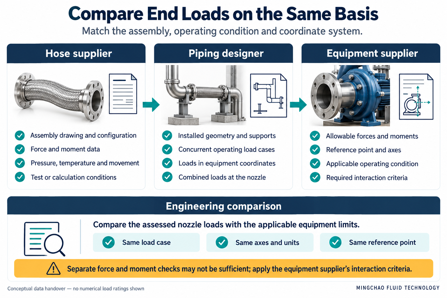
The illustration above shows the information exchanged between the hose supplier, piping designer and equipment supplier. The checks are review tasks, not confirmation that a particular assembly has passed.
6. Use a Defined Data Handover
| Responsible party | Required information |
|---|---|
| Hose supplier | Assembly configuration; applicable reaction or stiffness data; pressure, temperature, geometry and boundary conditions; included load effects |
| Piping designer | Installed route and supports; concurrent load cases; system reactions expressed at the equipment reference point |
| Equipment supplier | Allowable forces and moments; axes, reference point, operating conditions and combined-load acceptance criteria |
| Project reviewer | Traceable comparison, assumptions, unresolved inputs and recorded acceptance |
A concise supplier request is:
Please provide applicable end-force and end-moment data for the proposed assembly and installed geometry. State the pressure, temperature, movement, boundary conditions, reference points and load contributions included.
If the comparison fails, review routing, live length, hose construction or support design. Recheck pressure capability, bend radius and movement after any change. Do not force the flanges into alignment and treat the resulting fit as approval.
Project Information for Mingchao Review
For a JR Stainless Steel Flexible Metal Hose review, provide the equipment connection drawing, installed arrangement, operating conditions, required movement and equipment nozzle-load limits.
Identify any required reaction-data deliverable before ordering. A product datasheet or pressure-test record should not be assumed to include it.
Technical References and Related Resources
- Mingchao — JR Stainless Steel Flexible Metal Hose
- Mingchao — Live Length, Bend Radius and Installation Movement
- Mingchao — Technical Information & Engineering Resources
- Hose Master — Corrugated Metal Hose: Assembly Components and Value
- KSB — Pump Nozzle Load
External references support engineering principles. They do not establish Mingchao-specific stiffness, end reactions or equipment-load limits.
Mingchao Fluid Technology
www.mingchaoft.com