Metal Expansion Joints & Compensators
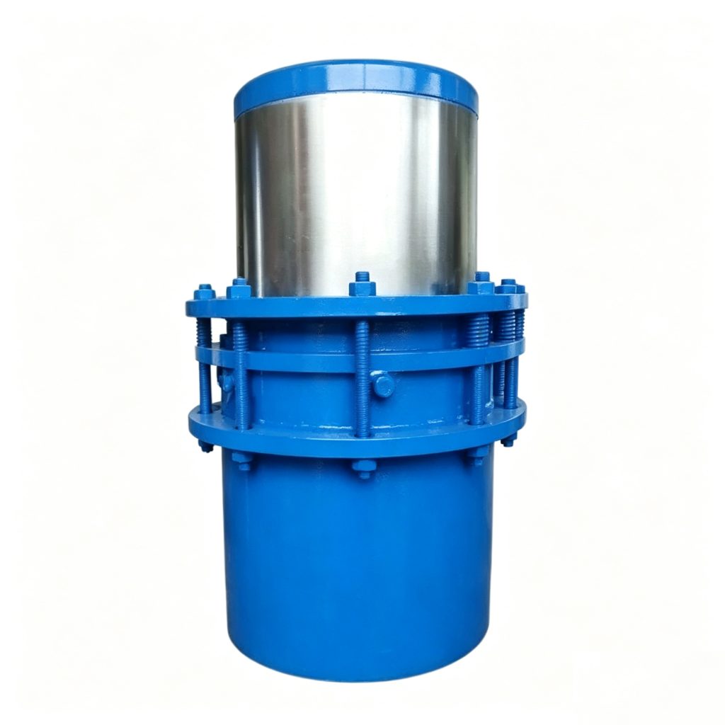
ZTB-B Direct-Buried Sleeve Expansion Joint
The Mingchao ZTB-B Direct-Buried Sleeve Expansion Joint accommodates axial thermal movement through controlled sliding between sleeve components. Catalog data covers DN15–DN1000, and Type I / Type II structural variants are available. Final selection must confirm travel, pressure, temperature, medium, installed length, preset position, sealing arrangement, anchors, guides and burial conditions.
Also searched as a sleeve expansion joint, sleeve compensator, slip-type expansion joint, packed slip expansion joint or sliding sleeve expansion joint. This product is not a metal bellows joint or a dismantling/telescopic joint.
- Model
- ZTB-B
- Variants
- Type I / Type II
- Size Range
- DN15–DN1000
- Primary Movement
- Axial Sliding
- Mechanism
- Core / Inner Sleeve + Outer Body
- Sealing
- Packing / Sealing System
- Connection
- Pipe-End / Welded Configuration
- Standard
- CJ/T 487-2015
Type I / Type II Project ConfigurationVariant, travel, length, packing, connection and operating conditions are confirmed against the approved drawing.
Project Configuration
Mingchao can customize the product configuration based on the technical information, operating conditions and dimensional data you provide. Final configuration can be reviewed and manufactured to the approved project drawing.
ZTB-B Direct-Buried Sleeve Expansion Joint Overview
The Mingchao ZTB-B Direct-Buried Sleeve Expansion Joint is an axial sliding compensator for thermal piping. It uses relative movement between sleeve components and a packing/sealing arrangement rather than a metal bellows.
The product is available as Type I and Type II structural variants. Mingchao catalog data covers DN15–DN1000 and documents project dimensions, axial travel and installed length.
The catalog identifies use in overhead and direct-buried piping, including urban heating and industrial systems. Final application suitability must be confirmed against the service and project drawing.
How a Sleeve Expansion Joint Accommodates Axial Movement
A sleeve expansion joint accommodates axial thermal movement through controlled relative sliding between its core or inner sleeve and outer body. A packing and sealing system maintains pressure containment around the moving sleeve.
This sliding mechanism—not bellows deformation—defines the ZTB-B product identity. Final performance depends on pressure, temperature, medium, movement, alignment, sealing arrangement and installation conditions.
| Specification | Confirmed Data |
|---|---|
| Product Type | Direct-Buried Sleeve Expansion Joint |
| Model | ZTB-B |
| Variants | Type I / Type II |
| Size Range | DN15–DN1000 |
| Primary Movement | Axial Sliding Movement |
| Mechanism | Core / Inner Sleeve Sliding within Outer Body |
| Sealing | Formed Packing with Semi-Solid Sealing Grease (catalog configuration) |
| Connection | Pipe-End / Welded Configuration |
| Standard | CJ/T 487-2015 |
ZTB-B Type I & Type II Structural Variants
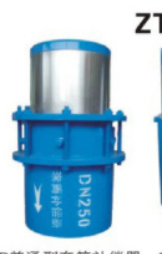
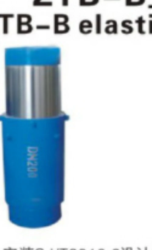
Type I and Type II structural variants are available. The required configuration should be confirmed from the project operating conditions and approved product drawing. The current source does not independently define a one-way/two-way or other engineering distinction, so no such difference is inferred.
Technical Data — Dimensions & Axial Travel
The table publishes the unambiguous p29 dimensions and axial travel for each documented nominal diameter.
| DN | Core Tube OD D2 (mm) | Flange OD D3 (mm) | Packing Chamber Length (mm) | Axial Travel (mm) | Installed Length (mm) |
|---|---|---|---|---|---|
| 15 | 18 | 95 | 36 | 130 | 640 |
| 20 | 23 | 105 | 36 | 130 | 640 |
| 25 | 30 | 115 | 36 | 130 | 640 |
| 32 | 36 | 120 | 36 | 130 | 640 |
| 36 | 43 | 125 | 36 | 130 | 640 |
| 40 | 48 | 130 | 36 | 130 | 640 |
| 50 | 55 | 160 | 56 | 150 | 720 |
| 65 | 71 | 180 | 56 | 150 | 720 |
| 70 | 74 | 190 | 56 | 150 | 720 |
| 80 | 87 | 195 | 56 | 150 | 720 |
| 100 | 106 | 215 | 56 | 200 | 820 |
| 125 | 131 | 245 | 56 | 200 | 820 |
| 150 | 157 | 280 | 56 | 200 | 820 |
| 175 | 192 | 335 | 70 | 200 | 820 |
| 200 | 217 | 335 | 70 | 200 | 820 |
| 225 | 242 | 390 | 70 | 200 | 820 |
| 250 | 270 | 390 | 70 | 200 | 820 |
| 300 | 322 | 440 | 91 | 200 | 820 |
| 350 | 373 | 500 | 91 | 200 | 820 |
| 400 | 426 | 565 | 91 | 200 | 820 |
| 450 | 478 | 615 | 91 | 200 | 820 |
| 500 | 528 | 670 | 91 | 250 | 920 |
| 600 | 630 | 780 | 91 | 250 | 920 |
| 700 | 720 | 880 | 91 | 250 | 920 |
| 800 | 820 | 990 | 112 | 250 | 920 |
| 900 | 920 | 1095 | 112 | 250 | 920 |
| 1000 | 1020 | 1195 | 112 | 250 | 920 |
Confirm D1 and maximum-friction values against the approved project data.
Sealing System, Sliding Surface & Project Configuration
The current Mingchao catalog describes a combined sealing arrangement using formed packing and semi-solid sealing grease around the sliding assembly. Exact packing grade, sealing material and project maintenance procedure must be confirmed for the selected service.
Do not assume universal leakage performance, online repacking, lifetime sealing or maintenance-free operation. The sliding surface, packing chamber, pressure, temperature, medium and preset position must be reviewed together.
Applications in District Heating, Steam & Hot-Water Piping
District-Heating Piping
Axial thermal movement in approved overhead or buried configurations.
Steam Piping
Only with a confirmed pressure, temperature and sealing configuration.
Hot-Water Utilities
Sliding compensation in thermal utility lines.
Urban Heating Networks
Project-specific axial movement and burial layout.
Industrial Thermal Piping
Metallurgical, power and process applications where service conditions are confirmed.
Replacement Projects
Review the existing dimensions, preset and sealing requirements.
Suitability depends on confirmed pressure, temperature, medium, sealing arrangement, movement and installation conditions.
How to Select a ZTB-B Sleeve Expansion Joint
Provide:
- DN / pipe size
- Type I or Type II, if already specified
- Required axial travel
- Design pressure
- Normal working pressure
- Operating temperature
- Process medium
- Required installed length
- Required preset position
- Buried or above-ground condition
- Pipe outside diameter / specification
- Pipe-end connection
- Anchor arrangement
- Guide arrangement
- Packing / sealing requirement, if specified
- Quantity and destination country
- Project drawing
- Testing and documentation requirements
Confirm the selected variant and all operating data against the approved product drawing.
ZTB-B Sleeve vs. JZM Direct-Buried Bellows Expansion Joint
| Selection Point | ZTB-B Sleeve Expansion Joint | JZM Direct-Buried Bellows |
|---|---|---|
| Movement mechanism | Controlled relative sliding of sleeve components | Metal bellows deformation |
| Pressure containment | Packing / sealing system around moving sleeve | Metal bellows pressure boundary |
| Primary movement | Axial | Axial |
| Selection focus | Travel, sealing, alignment, preset and piping layout | Bellows movement, pressure, casing and piping layout |
| Interchangeability | Not interchangeable without engineering review. | |
Pressure Thrust, Anchors & Pipe Guides
Anchors and pipe guides remain part of the piping-system design. Main anchors must address applicable pressure thrust, sliding friction and other system loads. Guides should maintain alignment and prevent uncontrolled lateral loading or rotation. The ZTB-B must not support pipe or equipment dead weight.
Installation, Preset Position, Inspection & Burial Considerations
Follow the approved ZTB-B drawing and piping-system design.
Identity
Verify ZTB-B, DN, Type I/II and travel.
Preset
Confirm installed and preset position before final connection.
Alignment
Keep the sleeve axis aligned with the pipeline.
No Lateral Loading
Do not use the joint for normal lateral or angular movement.
No Torsion
Do not twist the sliding assembly.
Anchors
Install system anchors for pressure thrust and friction loads.
Guides
Install guides to preserve axial sliding.
Independent Support
Support pipe and equipment independently.
Sliding Surface
Protect the exposed sliding surface from impact, dirt and scoring.
Packing
Confirm packing/sealing condition before burial or insulation.
Burial
Coordinate casing, access, insulation and corrosion protection.
Testing
Follow the approved pressure/leak-test procedure.
Inspection
Inspect pipe ends, body, packing area and movement components before service.
Real Product Photos, Drawings & Technical References
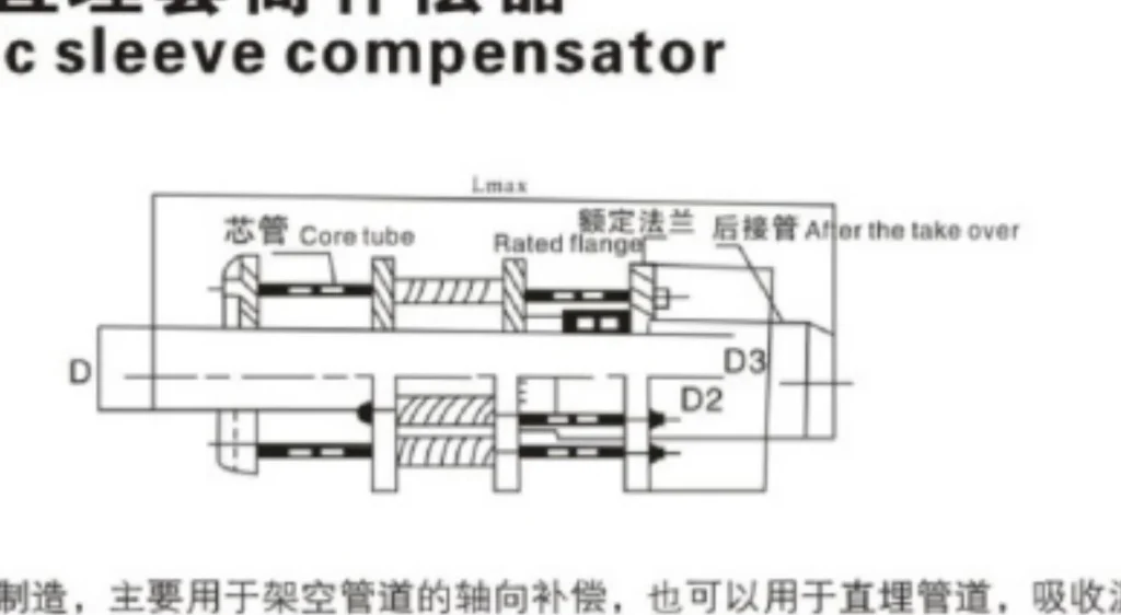
The legacy catalog standard CJ/T 3016.2-1994 is replaced on this page by the currently effective CJ/T 487-2015. Confirm D1 and friction values against the approved project data.
Product Photos
Technical Datasheet
ZTB-B Direct-Buried Sleeve Expansion Joint
Technical Datasheet · PDF