
Metal Expansion Joints & Compensators
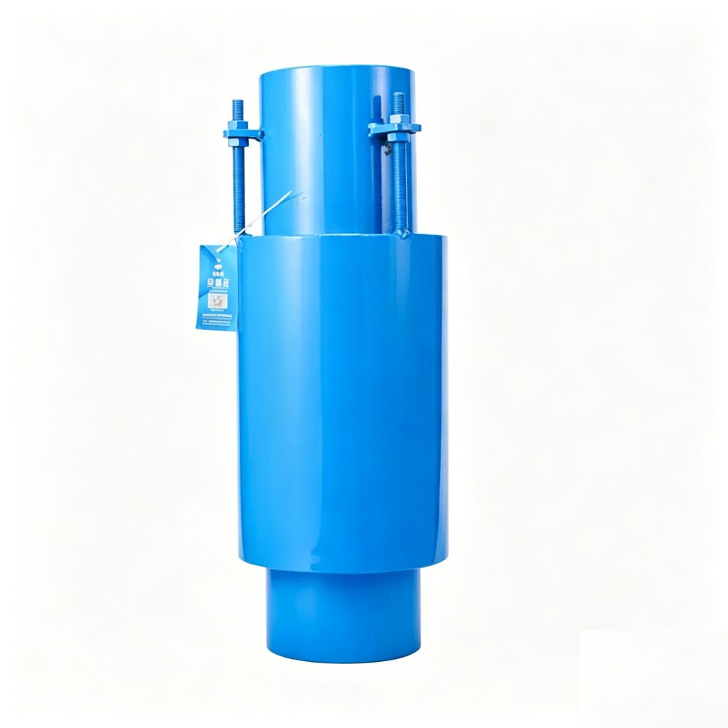
JZM Direct-Buried Corrugated Expansion Joint
The Mingchao JZM Direct-Buried Corrugated Expansion Joint is a metal bellows expansion joint with an integrated protective casing for axial thermal movement in underground piping. Catalog configurations cover DN50–DN1000 and pressure levels from 0.25 to 2.5 MPa. Final selection must consider movement, pressure, temperature, medium, burial conditions, insulation interfaces, anchors and piping layout.
Also searched as a direct-buried bellows expansion joint, buried expansion joint, underground bellows expansion joint or buried axial expansion joint.
- Model
- JZM
- Size Range
- DN50–DN1000
- Primary Movement
- Axial
- Pressure Levels
- 0.25 / 0.6 / 1.0 / 1.6 / 2.5 MPa
- Flexible Element
- Metal Bellows
- Protection
- Integrated Outer Casing
- Connection
- Pipe-End Configuration
- Standard
- GB/T 12777-2019
Project ConfigurationMovement, pressure level, wave number, length, casing and pipe-end details are reviewed against confirmed project requirements.
Project Configuration
Mingchao can customize the product configuration based on the technical information, operating conditions and dimensional data you provide. Final configuration can be reviewed and manufactured to the approved project drawing.
JZM Direct-Buried Bellows Expansion Joint Overview
The Mingchao JZM Direct-Buried Corrugated Expansion Joint is designed for axial thermal movement in underground piping.
Its flexible element is a metal bellows. A protective outer casing surrounds the movement assembly for the direct-buried installation context. This product is technically distinct from a sliding sleeve compensator.
Mingchao catalog data covers DN50–DN1000 with multiple wave-number and length configurations across 0.25, 0.6, 1.0, 1.6 and 2.5 MPa pressure levels.
Direct-Buried Bellows Construction & Protective Casing
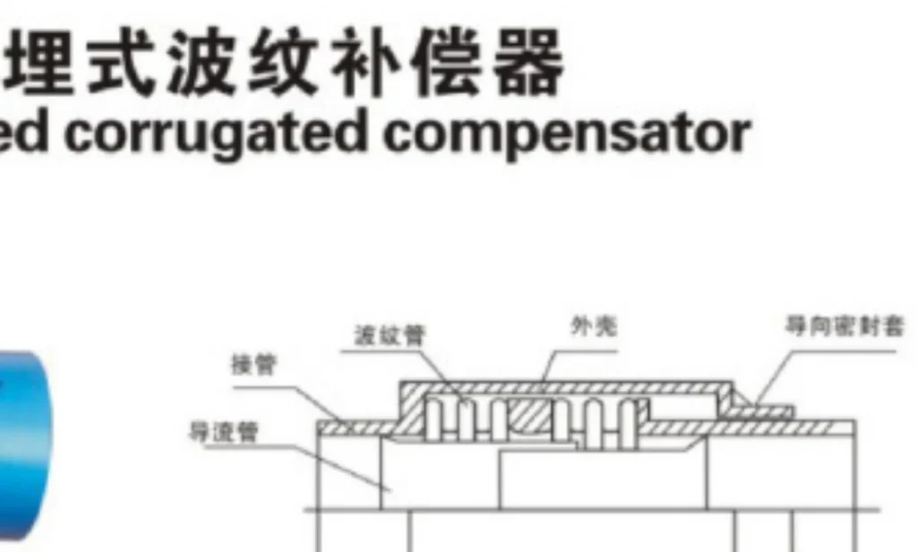
The JZM uses a metal bellows as the flexible element and an integrated outer casing to protect the movement assembly in direct-buried service. The catalog drawing identifies the bellows, outer casing, pipe-end components and internal guiding arrangement.
The casing does not turn the product into a sleeve compensator. Axial movement is produced by bellows deformation, and the approved drawing must govern flow direction, installed length and connection details.
| Specification | Confirmed Data |
|---|---|
| Product Type | Direct-Buried Corrugated / Bellows Expansion Joint |
| Model | JZM |
| Size Range | DN50–DN1000 |
| Pressure Levels | 0.25 / 0.6 / 1.0 / 1.6 / 2.5 MPa |
| Primary Movement | Axial |
| Flexible Element | Metal Bellows |
| Protection | Integrated Outer Casing |
| Connection | Pipe-End Configuration |
| Standard | GB/T 12777-2019 |
Technical Data — Axial Compensation & Dimensions
Each pressure-level entry is shown as axial compensation (mm) / stiffness (N/mm), exactly as documented for the selected DN and wave number.
| DN | Wave Number | 0.25 MPa Movement / Stiffness | 0.6 MPa Movement / Stiffness | 1.0 MPa Movement / Stiffness | 1.6 MPa Movement / Stiffness | 2.5 MPa Movement / Stiffness | Effective Area (cm²) | Max OD (mm) | Pipe End (mm) | Total Length (mm) |
|---|---|---|---|---|---|---|---|---|---|---|
| 50 | 8 | 14/153 | 12/318 | 12/318 | 12/635 | 11/1310 | 37 | 120 | Ø57x3.5 | 361 |
| 50 | 16 | 27/76 | 24/158 | 24/158 | 24/318 | 23/655 | 37 | 120 | Ø57x3.5 | 445 |
| 50 | 32 | 52/38 | 48/79 | 48/79 | 48/159 | 46/328 | 37 | 120 | Ø57x3.5 | 621 |
| 65 | 8 | 19/213 | 18/213 | 18/213 | 18/424 | 16/841 | 55 | 159 | Ø73x4 | 377 |
| 65 | 12 | 30/142 | 29/142 | 27/142 | 27/283 | 25/421 | 55 | 159 | Ø73x4 | 425 |
| 65 | 24 | 60/71 | 58/107 | 54/107 | 54/142 | 50/211 | 55 | 159 | Ø73x4 | 581 |
| 80 | 8 | 30/179 | 30/179 | 30/358 | 29/358 | 27/650 | 81 | 162 | Ø89x4 | 430 |
| 80 | 10 | 54/143 | 37/143 | 37/286 | 37/286 | 32/325 | 81 | 162 | Ø89x4 | 466 |
| 80 | 20 | 108/72 | 74/72 | 74/143 | 74/143 | 64/163 | 81 | 162 | Ø89x4 | 660 |
| 100 | 6 | 34/138 | 34/277 | 33/417 | 33/417 | 32/817 | 121 | 180 | Ø108x4 | 410 |
| 100 | 10 | 56/83 | 56/166 | 56/250 | 54/250 | 50/409 | 121 | 180 | Ø108x4 | 492 |
| 100 | 20 | 112/42 | 112/83 | 112/125 | 108/125 | 100/205 | 121 | 180 | Ø108x4 | 712 |
| 125 | 5 | 37/136 | 36/272 | 36/408 | 35/408 | 33/801 | 180 | 221 | Ø133x4 | 410 |
| 125 | 9 | 66/76 | 65/151 | 65/227 | 63/227 | 60/401 | 180 | 221 | Ø133x4 | 412 |
| 125 | 18 | 132/38 | 130/76 | 130/114 | 126/114 | 120/201 | 180 | 221 | Ø133x4 | 711 |
| 150 | 5 | 49/100 | 49/200 | 48/300 | 45/456 | 44/845 | 257 | 245 | Ø159x4.5 | 433 |
| 150 | 8 | 88/63 | 78/125 | 77/188 | 71/286 | 65/423 | 257 | 245 | Ø159x4.5 | 518 |
| 150 | 16 | 159/32 | 156/63 | 154/94 | 142/143 | 130/211 | 257 | 245 | Ø159x4.5 | 756 |
| 200 | 4 | 58/95 | 56/193 | 56/288 | 56/450 | 55/800 | 479 | 327 | Ø219x6 | 475 |
| 200 | 6 | 86/63 | 85/128 | 85/192 | 84/320 | 80/927 | 479 | 327 | Ø219x6 | 553 |
| 200 | 12 | 172/32 | 170/64 | 170/96 | 168/160 | 160/200 | 479 | 327 | Ø219x6 | 800 |
| 250 | 4 | 75/170 | 74/343 | 63/588 | 53/930 | 50/1856 | 769 | 404 | Ø273x8 | 500 |
| 250 | 6 | 112/113 | 110/228 | 95/392 | 80/620 | 78/927 | 769 | 404 | Ø273x8 | 620 |
| 250 | 12 | 220/57 | 220/114 | 190/196 | 160/310 | 156/464 | 769 | 404 | Ø273x8 | 984 |
| 300 | 4 | 73/250 | 72/503 | 65/830 | 57/1253 | 54/2142 | 1106 | 451 | Ø325x8 | 584 |
| 300 | 6 | 110/167 | 109/335 | 97/553 | 85/835 | 80/1071 | 1106 | 451 | Ø325x8 | 713 |
| 300 | 12 | 220/84 | 218/168 | 194/277 | 170/418 | 160/536 | 1106 | 451 | Ø325x8 | 1116 |
| 350 | 4 | 79/263 | 78/523 | 72/840 | 64/1265 | 62/2684 | 1307 | 500 | Ø377x10 | 614 |
| 350 | 6 | 119/175 | 117/348 | 107/560 | 97/843 | 90/1342 | 1307 | 500 | Ø377x10 | 759 |
| 350 | 12 | 238/88 | 234/174 | 214/280 | 194/442 | 180/671 | 1307 | 500 | Ø377x10 | 1216 |
| 400 | 4 | 83/280 | 73/458 | 70/918 | 65/1373 | 63/3675 | 1611 | 537 | Ø426x10 | 625 |
| 400 | 6 | 125/187 | 109/305 | 102/612 | 97/915 | 90/1838 | 1611 | 537 | Ø426x10 | 771 |
| 400 | 12 | 250/94 | 218/153 | 204/306 | 194/458 | 180/920 | 1611 | 537 | Ø426x10 | 1225 |
| 450 | 4 | 98/203 | 96/405 | 82/680 | 69/2305 | 65/4350 | 1972 | 632 | Ø478x10 | 620 |
| 450 | 6 | 147/135 | 144/270 | 124/460 | 103/1537 | 90/2175 | 1972 | 632 | Ø478x10 | 762 |
| 450 | 12 | 294/68 | 288/135 | 248/230 | 206/769 | 180/1087 | 1972 | 632 | Ø478x10 | 1200 |
| 500 | 4 | 102/212 | 100/423 | 84/728 | 70/2452 | 65/4266 | 2445 | 699 | Ø529x10 | 624 |
| 500 | 6 | 153/142 | 149/282 | 126/485 | 105/1635 | 90/2128 | 2445 | 699 | Ø529x10 | 766 |
| 500 | 12 | 306/71 | 298/141 | 252/243 | 210/818 | 180/1064 | 2445 | 699 | Ø529x10 | 1216 |
| 600 | 4 | 123/265 | 121/530 | 86/1468 | 99/1740 | 95/2842 | 3534 | 806 | Ø630x10 | 676 |
| 600 | 6 | 185/177 | 181/353 | 148/978 | 140/1160 | 120/1420 | 3534 | 806 | Ø630x10 | 848 |
| 600 | 12 | 370/89 | 362/177 | 358/489 | 280/580 | 240/710 | 3534 | 806 | Ø630x10 | 1382 |
| 700 | 4 | 128/287 | 126/573 | 87/1625 | 85/2972 | 84/4100 | 4717 | 915 | Ø720x10 | 708 |
| 700 | 6 | 192/192 | 188/382 | 168/1083 | 131/1982 | 120/2050 | 4717 | 915 | Ø720x10 | 882 |
| 700 | 12 | 384/96 | 376/191 | 336/542 | 262/991 | 4717 | 915 | Ø720x10 | 1422 | |
| 800 | 4 | 128/310 | 126/620 | 84/1778 | 85/3183 | 84/6234 | 5822 | 1005 | Ø820x10 | 724 |
| 800 | 8 | 256/155 | 252/310 | 168/889 | 170/1591 | 168/3117 | 5822 | 1005 | Ø820x10 | 1071 |
| 800 | 12 | 384/103 | 378/207 | 252/596 | 241/1061 | 236/1558 | 5822 | 1005 | Ø820x10 | 1538 |
| 900 | 4 | 151/378 | 149/758 | 118/1329 | 117/2575 | 7620 | 1137 | Ø920x10 | 792 | |
| 900 | 8 | 302/189 | 298/379 | 236/664 | 234/1288 | 7620 | 1137 | Ø920x10 | 1211 | |
| 900 | 12 | 453/126 | 447/253 | 351/443 | 354/825 | 7620 | 1137 | Ø920x10 | 1650 | |
| 1000 | 4 | 140/423 | 140/845 | 115/2770 | 90/5038 | 9043 | 1227 | Ø1020x10 | 800 | |
| 1000 | 8 | 280/212 | 280/423 | 230/1385 | 180/2519 | 9043 | 1227 | Ø1020x10 | 1200 | |
| 1000 | 12 | 420/141 | 420/282 | 345/923 | 270/1679 | 9043 | 1227 | Ø1020x10 | 1616 |
Blank cells indicate values requiring factory confirmation; no unverified values are supplied.
Buried Installation, Alignment & Piping Layout
- Maintain the specified axial alignment and installed length.
- Coordinate the outer casing with the trench, insulation and surrounding pipeline system.
- Prevent soil, water and construction loads from damaging the moving assembly.
- Confirm fixed points, anchors and directional guides before installation.
- Do not force major pipe misalignment into the expansion joint.
Applications in District Heating & Underground Thermal Piping
District-Heating Piping
Direct-buried axial thermal movement where project scope is confirmed.
Underground Hot-Water Piping
Bellows compensation with a protected movement assembly.
Thermal Utility Lines
Axial movement in buried utility piping.
Industrial Underground Piping
Project-specific buried piping connections.
Steam and Condensate Networks
Only where the selected configuration and service conditions are confirmed.
Replacement Projects
Review the existing drawing, installed length and burial interface.
Suitability depends on confirmed pressure, temperature, medium, movement, insulation and burial conditions.
How to Select a JZM Direct-Buried Expansion Joint
Provide:
- DN / pipe size
- Required axial movement
- Design pressure
- Normal working pressure
- Operating temperature
- Process medium
- Required installed length
- Buried / trench condition
- Pipeline insulation system
- Outer casing / interface requirement
- Pipe outside diameter / specification
- Pipe-end connection
- Flow direction
- Anchor / fixed-point arrangement
- Guide arrangement
- Project environment
- Quantity and destination country
- Project drawings
- Testing requirements
- Documentation requirements
Confirm all operating and burial-layout data before production.
JZM Bellows vs. ZTB-B Sleeve Expansion Joint
| Selection Point | JZM Direct-Buried Bellows | ZTB-B Direct-Buried Sleeve |
|---|---|---|
| Movement mechanism | Metal bellows deformation | Controlled sliding between sleeve components |
| Primary identity | Buried bellows expansion joint | Buried sleeve / slip-type expansion joint |
| Selection | Bellows movement, pressure, casing and piping layout | Axial travel, sealing arrangement, alignment and piping layout |
| Interchangeability | Not interchangeable without engineering review. | |
JZM vs. Conventional Axial Bellows Expansion Joint
| Point | JZM Direct-Buried | JDZ Conventional Axial |
|---|---|---|
| Installation context | Underground/direct-buried service with an outer casing | Conventional piping installation |
| Primary movement | Axial | Axial |
| Selection | Includes burial, casing and insulation interfaces | Uses JDZ product-specific piping conditions |
Pressure Thrust, Anchors & Guides
Direct burial does not remove pressure thrust. Main anchors and fixed points must be designed for the applicable pressure thrust, bellows spring force and other piping loads. Directional guides should preserve the intended axial movement path, while piping and connected equipment remain independently supported.
Installation, Insulation & Corrosion Protection
Follow the approved JZM drawing and project piping design.
Identity
Verify model, DN, pressure level, wave number and length.
Alignment
Maintain the intended axial piping line.
No Torsion
Do not twist the assembly.
Flow
Confirm the marked flow direction.
Anchors
Install required anchors or fixed points.
Guides
Maintain the approved movement path.
Support
Support connected piping independently.
Insulation Interface
Coordinate insulation without obstructing movement.
Corrosion Protection
Protect casing, pipe ends and welds for the site environment.
Burial
Prevent uncontrolled soil or construction load on the movement assembly.
Testing
Use the approved pressure/leak-test procedure.
Inspection
Inspect casing, pipe ends, welds and movement components before burial and service.
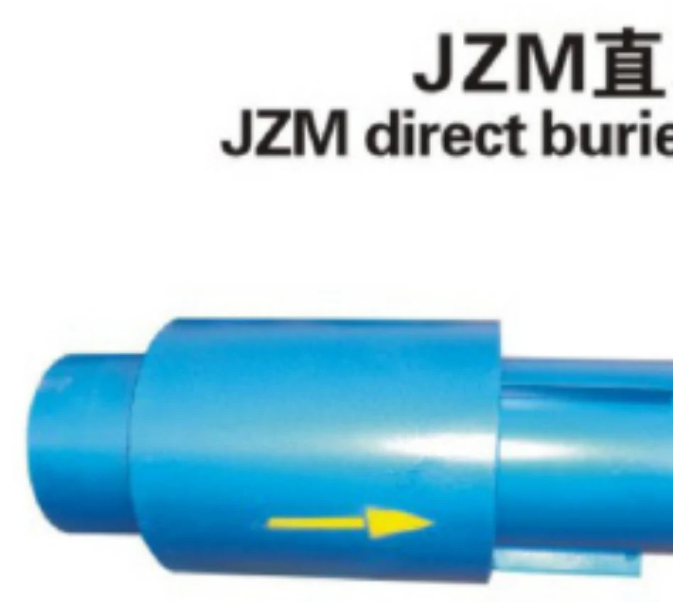
Real Product Photos, Drawings & Technical References
Technical Datasheet
JZM Direct-Buried Corrugated Expansion Joint
Technical Datasheet · PDF