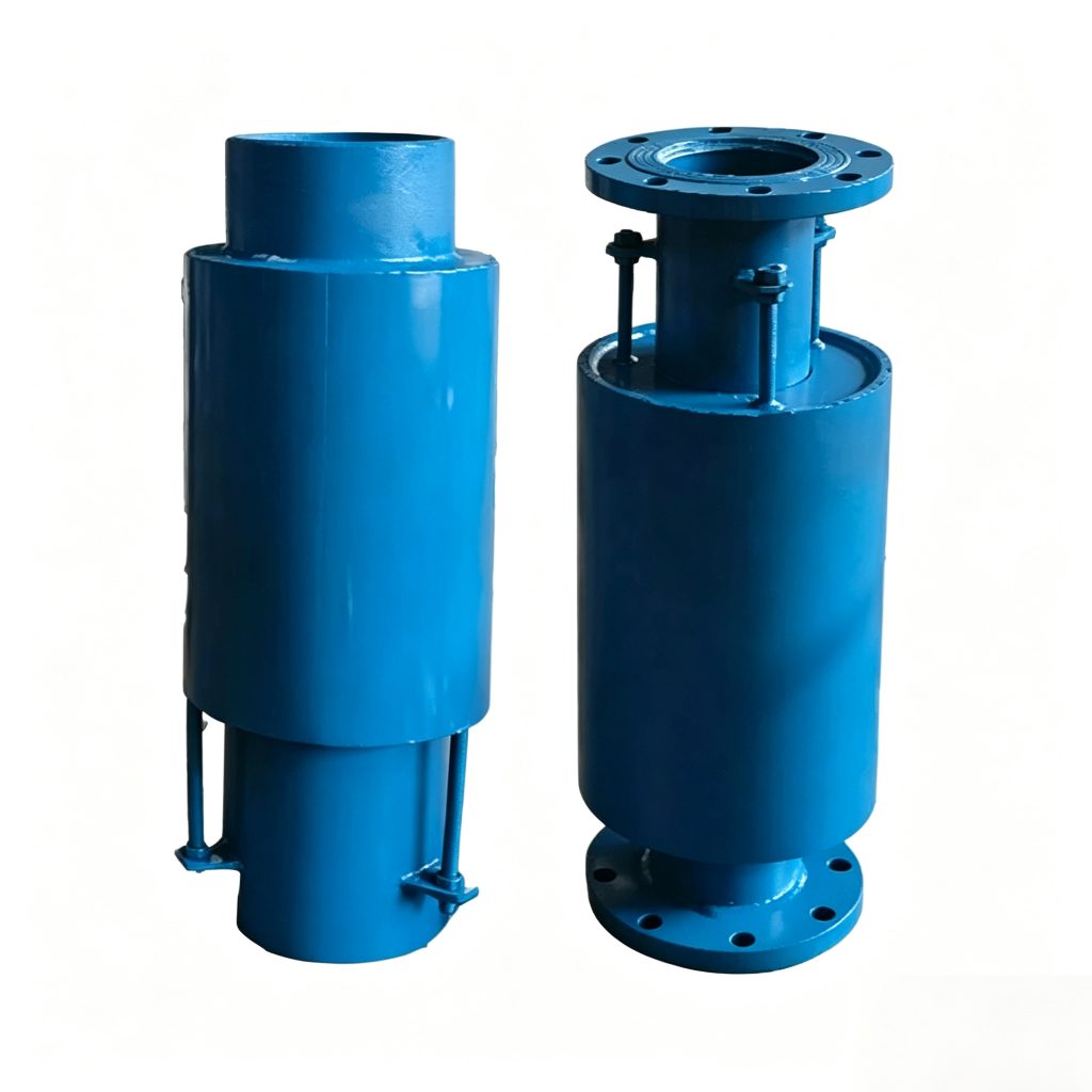
Metal Expansion Joints & Compensators
JZW Externally Pressurized Axial Expansion Joint
The Mingchao JZW Externally Pressurized Axial Expansion Joint is designed for straight piping systems that require substantial axial thermal movement. Process pressure is routed to act on the outside of the bellows, improving bellows stability for long-stroke axial compensation. Current Mingchao catalog data covers DN50–DN1500 with 0.6, 1.0 and 1.6 MPa pressure levels. Final selection should be confirmed against operating pressure, temperature, process medium, required axial movement, installed length, pipe-end requirements, anchors, guides and piping layout.
Also searched as an external pressure expansion joint, externally pressurized bellows expansion joint, long-stroke expansion joint or externally pressurized compensator.
- Model
- JZW
- Size Range
- DN50–DN1500
- Movement
- Axial
- Pressure Levels
- 0.6 / 1.0 / 1.6 MPa
- Configuration
- Externally Pressurized Bellows
- Catalog Axial Compensation
- Up to 460 mm in Specific Configurations
- Connection
- Pipe-End Configuration
- Standard
- GB/T 12777-2019
Project ConfigurationConfiguration is reviewed against confirmed project requirements.
Project Configuration
Mingchao can customize the product configuration based on the technical information, operating conditions and dimensional data you provide. Final configuration can be reviewed and manufactured to the approved project drawing.
JZW Externally Pressurized Expansion Joint Overview
The Mingchao JZW Externally Pressurized Axial Expansion Joint is designed for straight piping systems that require substantial axial thermal movement.
Unlike a conventional internally pressurized axial bellows joint, process pressure in the JZW configuration acts on the outside of the bellows.
This arrangement improves the stability of longer multi-convolution bellows and allows greater axial movement to be accommodated within the selected piping configuration.
Current Mingchao catalog data covers DN50–DN1500 and pressure levels of 0.6, 1.0 and 1.6 MPa, with multiple length and wave-number configurations.
Final selection should consider pressure, temperature, process medium, required axial movement, installed length, connection requirements, anchors, guides and piping layout.
How External Pressurization Improves Bellows Stability
In an externally pressurized expansion joint, process pressure is routed so that it acts on the external surface of the bellows. This differs from a conventional internally pressurized axial expansion joint, where process pressure acts on the inner surface of the bellows.
External pressurization improves the pressure stability of longer bellows configurations and makes larger axial travel practical for applications where the piping system has been designed for this type of joint.
External pressurization does not make the expansion joint pressure-balanced. Pressure thrust, spring force, anchors, guides and connected-equipment loads must still be considered in the piping-system design.
| Specification | Confirmed Product Data |
|---|---|
| Product Type | Externally Pressurized Axial Expansion Joint |
| Model | JZW |
| Size Range | DN50–DN1500 |
| Pressure Levels | 0.6 / 1.0 / 1.6 MPa |
| Primary Movement | Axial |
| Bellows Arrangement | Externally Pressurized |
| Catalog Configurations | Multiple Lengths and Wave Numbers |
| Connection | Pipe-End Configuration |
| Maximum Documented Axial Compensation | Up to 460 mm in specific catalog configurations |
| Standard | GB/T 12777-2019 |
| Selection Basis | DN / Pressure / Temperature / Medium / Required Axial Movement / Installed Length / Anchors / Guides / Piping Layout |
| Customization | According to confirmed project requirements |
JZW Construction & Flow Path
The JZW combines an externally pressurized bellows arrangement with an outer casing and pipe-end components that route the process medium through the assembly. The outer casing protects and contains the external-pressure configuration while the bellows provides the required axial flexibility.
The Mingchao catalog drawing identifies the inlet end pipe, inlet ring, guide tube, limit ring, bellows, outer tube, outlet ring and outlet end pipe. Flow direction must be confirmed against the approved JZW drawing before installation.
No unverified material grade is claimed.
Technical Data — Axial Compensation & Stiffness
The Mingchao JZW catalog provides multiple length and wave-number configurations by nominal size. For each documented configuration, the catalog lists axial compensation and stiffness values at 0.6, 1.0 and 1.6 MPa pressure levels.
| DN | Length (mm) | Wave Number | 0.6 MPa — Compensation (mm) / Stiffness (N/mm) | 1.0 MPa — Compensation (mm) / Stiffness (N/mm) | 1.6 MPa — Compensation (mm) / Stiffness (N/mm) | Maximum External Diameter (mm) |
|---|---|---|---|---|---|---|
| 50 | 432 | 10 | 41 / 231 | 39 / 255 | 37 / 286 | 270 |
| 50 | 654 | 20 | 82 / 116 | 78 / 126 | 74 / 143 | 270 |
| 65 | 488 | 10 | 41 / 231 | 39 / 255 | 37 / 286 | 290 |
| 65 | 756 | 20 | 82 / 116 | 78 / 126 | 74 / 143 | 290 |
| 80 | 506 | 9 | 56 / 196 | 53 / 232 | 50 / 278 | 308 |
| 80 | 789 | 18 | 112 / 98 | 106 / 116 | 100 / 139 | 308 |
| 100 | 532 | 8 | 61 / 167 | 57 / 218 | 54 / 256 | 336 |
| 100 | 789 | 16 | 122 / 84 | 114 / 109 | 108 / 128 | 336 |
| 125 | 616 | 8 | 82 / 278 | 78 / 301 | 75 / 320 | 368 |
| 125 | 966 | 16 | 164 / 129 | 156 / 151 | 150 / 160 | 368 |
| 150 | 950 | 8 | 124 / 125 | 112 / 154 | 89 / 330 | 450 |
| 150 | 1540 | 16 | 250 / 56 | 210 / 87 | 160 / 113 | 450 |
| 200 | 950 | 8 | 130 / 155 | 100 / 126 | 70 / 409 | 505 |
| 200 | 1550 | 16 | 250 / 75 | 200 / 113 | 160 / 205 | 505 |
| 250 | 1080 | 8 | 161 / 111 | 130 / 162 | 105 / 378 | 566 |
| 250 | 1800 | 16 | 320 / 51 | 260 / 94 | 201 / 179 | 566 |
| 300 | 1090 | 8 | 161 / 138 | 130 / 194 | 100 / 338 | 600 |
| 300 | 1820 | 16 | 320 / 54 | 260 / 100 | 200 / 168 | 600 |
| 350 | 1090 | 8 | 165 / 165 | 132 / 221 | 99 / 438 | 676 |
| 350 | 1820 | 16 | 320 / 71 | 250 / 121 | 200 / 218 | 676 |
| 400 | 1110 | 8 | 162 / 164 | 132 / 290 | 101 / 468 | 710 |
| 400 | 1840 | 16 | 310 / 76 | 251 / 145 | 190 / 268 | 710 |
| 450 | 1110 | 8 | 152 / 131 | 124 / 339 | 100 / 532 | 768 |
| 450 | 1840 | 16 | 301 / 81 | 251 / 170 | 190 / 245 | 768 |
| 500 | 1475 | 6 | 190 / 180 | 150 / 515 | 150 / 765 | 975 |
| 500 | 2450 | 12 | 371 / 90 | 300 / 175 | 300 / 298 | 975 |
| 600 | 1540 | 6 | 195 / 231 | 150 / 754 | 140 / 765 | 1090 |
| 600 | 2540 | 12 | 391 / 121 | 290 / 364 | 280 / 480 | 1090 |
| 700 | 1540 | 6 | 200 / 222 | 155 / 601 | 150 / 832 | 1190 |
| 700 | 2540 | 12 | 400 / 112 | 300 / 400 | 290 / 478 | 1190 |
| 800 | 1540 | 6 | 201 / 200 | 164 / 497 | 150 / 897 | 1290 |
| 800 | 2540 | 12 | 400 / 135 | 321 / 451 | 299 / 583 | 1290 |
| 900 | 1605 | 6 | 220 / 206 | 230 / 635 | 220 / 765 | 1460 |
| 900 | 2685 | 12 | 430 / 154 | 460 / 337 | 442 / 388 | 1460 |
| 1000 | 1605 | 6 | 220 / 356 | 230 / 615 | 220 / 763 | 1560 |
| 1000 | 2685 | 12 | 430 / 268 | 460 / 303 | 442 / 418 | 1560 |
| 1100 | 1605 | 6 | 210 / 273 | 230 / 654 | 221 / 754 | 1660 |
| 1100 | 2685 | 12 | 428 / 187 | 460 / 347 | 442 / 414 | 1660 |
| 1200 | 1605 | 6 | 210 / 308 | 230 / 757 | 221 / 832 | 1780 |
| 1200 | 2685 | 12 | 420 / 104 | 460 / 488 | 443 / 601 | 1780 |
| 1300 | 1605 | 6 | 220 / 356 | 230 / 864 | 221 / 864 | 1860 |
| 1300 | 2685 | 12 | 410 / 132 | 450 / 432 | 435 / 626 | 1860 |
| 1400 | 1605 | 6 | 212 / 398 | 231 / 645 | 226 / 889 | 1960 |
| 1400 | 2685 | 12 | 410 / 198 | 450 / 466 | 430 / 665 | 1960 |
| 1500 | 1605 | 6 | 201 / 321 | 230 / 978 | 220 / 978 | 2060 |
| 1500 | 2685 | 12 | 400 / 187 | 449 / 422 | 432 / 665 | 2060 |
Axial compensation and stiffness are configuration-specific. Do not select one value independently of nominal size, pressure level, installed length and wave number. The Effective Bellows Area data is not displayed while a source inconsistency is being verified.
Large Axial Movement for Long Piping Runs
Externally pressurized expansion joints are particularly useful where a straight piping run requires greater axial thermal movement than is practical with a shorter conventional bellows configuration.
Mingchao’s current JZW catalog documents axial compensation values up to 460 mm in specific configurations. This does not mean that every JZW size or pressure level provides 460 mm of movement.
The required movement should be calculated from the actual piping temperature change and system geometry, then matched to the appropriate JZW size, pressure level, length and wave number.
Applications in Steam, Utility & Industrial Piping
Steam Distribution & Condensate
Axial thermal compensation in steam-distribution and steam-condensate piping.
Hot-Water & Thermal Utilities
Long-stroke axial movement in hot-water and thermal utility piping.
Long Industrial Piping Runs
Substantial axial thermal movement in straight industrial piping runs.
Power & Utility Piping
Axial compensation in power-plant and utility piping after full system review.
Petrochemical & Process Piping
Project-specific service where materials and operating conditions are confirmed.
Industrial Heating & Cooling
Axial thermal compensation in long industrial heating and cooling lines.
Application suitability depends on the confirmed pressure, temperature, medium, material configuration, movement and piping-system design.
How to Select a JZW Expansion Joint
Provide these engineering inputs for review.
- DN / pipe size
- Required axial compression
- Required axial extension
- Total calculated thermal movement
- Design pressure
- Normal working pressure
- Operating temperature
- Process medium
- Required installed or face-to-face length
- Pipeline length between anchors
- Pipe outside diameter / pipe specification where required
- Required pipe-end or connection configuration
- Flow direction
- Installation orientation
- Main anchor arrangement
- Intermediate / directional guide arrangement
- Quantity and destination country
- Project drawing, standard, testing and documentation requirements
Providing the calculated movement together with the piping layout and anchor/guide information allows the JZW configuration to be reviewed before quotation.
JZW External Pressure vs. JDZ Internal Pressure Expansion Joint
| Selection Point | JZW Externally Pressurized | JDZ Internal-Pressure Axial |
|---|---|---|
| Pressure on Bellows | Outside | Inside |
| Primary Movement | Axial | Axial |
| Typical Selection Need | Large / long-stroke axial thermal movement | Conventional axial thermal compensation |
| Bellows Stability | External pressure improves stability for longer bellows | Long internally pressurized bellows require pressure-stability review |
| Pressure Thrust | Must be considered by piping-system design | Must be considered by piping-system design |
| Anchors / Guides | Required according to system design | Required according to system design |
| Product Identity | Externally pressurized bellows compensator | Internally pressurized axial bellows compensator |
JZW and JDZ should not be selected interchangeably only from nominal pipe size or pressure level.
Pressure Thrust, Anchors & Pipe Guides
External pressure improves bellows stability; it does not eliminate piping pressure thrust.
- Piping and connected equipment should be independently supported.
- Main anchors must be designed for the applicable pressure thrust, bellows spring force and other piping-system loads.
- Pipe guides should maintain the intended axial movement path and prevent uncontrolled lateral displacement or misalignment.
- The JZW should not support pipe or equipment dead weight.
- Do not use the expansion joint to correct severe piping misalignment.
Installation, Flow Direction & Inspection
Install only against the approved JZW drawing and piping-system design.
Identity
Verify Model JZW, DN, pressure level and required movement.
Drawing
Confirm the approved product drawing.
Flow Direction
Confirm process flow direction.
Axial Line
Install in the intended axial piping line.
No Lateral Compensation
Do not apply lateral movement as normal JZW compensation.
No Angular Compensation
Do not apply angular movement as normal JZW compensation.
No Torsion
Do not twist the joint.
Alignment
Do not force piping misalignment into the joint.
Anchors & Guides
Install required anchors and guides before system pressure testing where applicable.
Independent Support
Support piping and equipment independently.
Installed Length
Verify installed / neutral length.
Lifting
Protect outer casing and pipe ends during lifting.
Damage Protection
Do not damage bellows, casing or weld areas.
Transport Hardware
Do not modify transport or limit hardware without confirmation.
Testing
Pressure or leak testing must follow the approved project and product procedure.
Inspection
Inspect pipe ends, casing, welds and movement components before service.
Real Product Photos, Drawings & Technical References
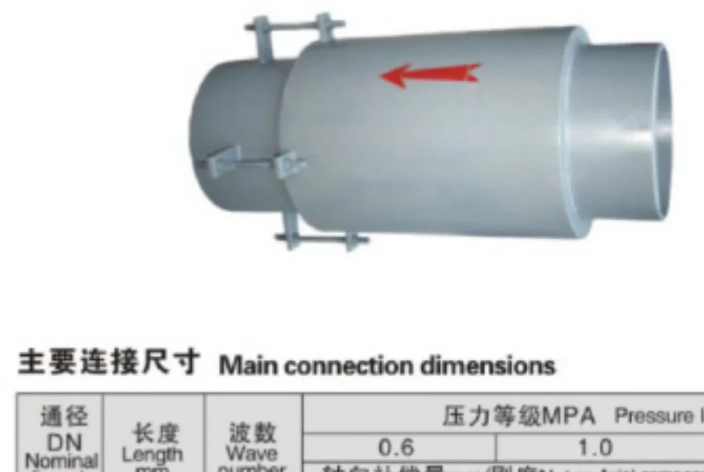
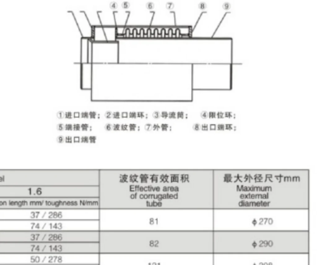
Technical table values are published for reference. Confirm the affected Effective Bellows Area value against factory data before selection.
Technical Datasheet
JZW Externally Pressurized Axial Expansion Joint
Technical Datasheet · PDF