Rubber Expansion Joints
JGD (KXT) Clamp-Type Rubber Expansion Joint
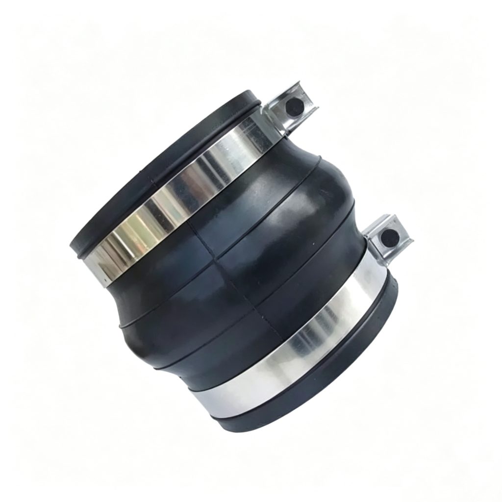
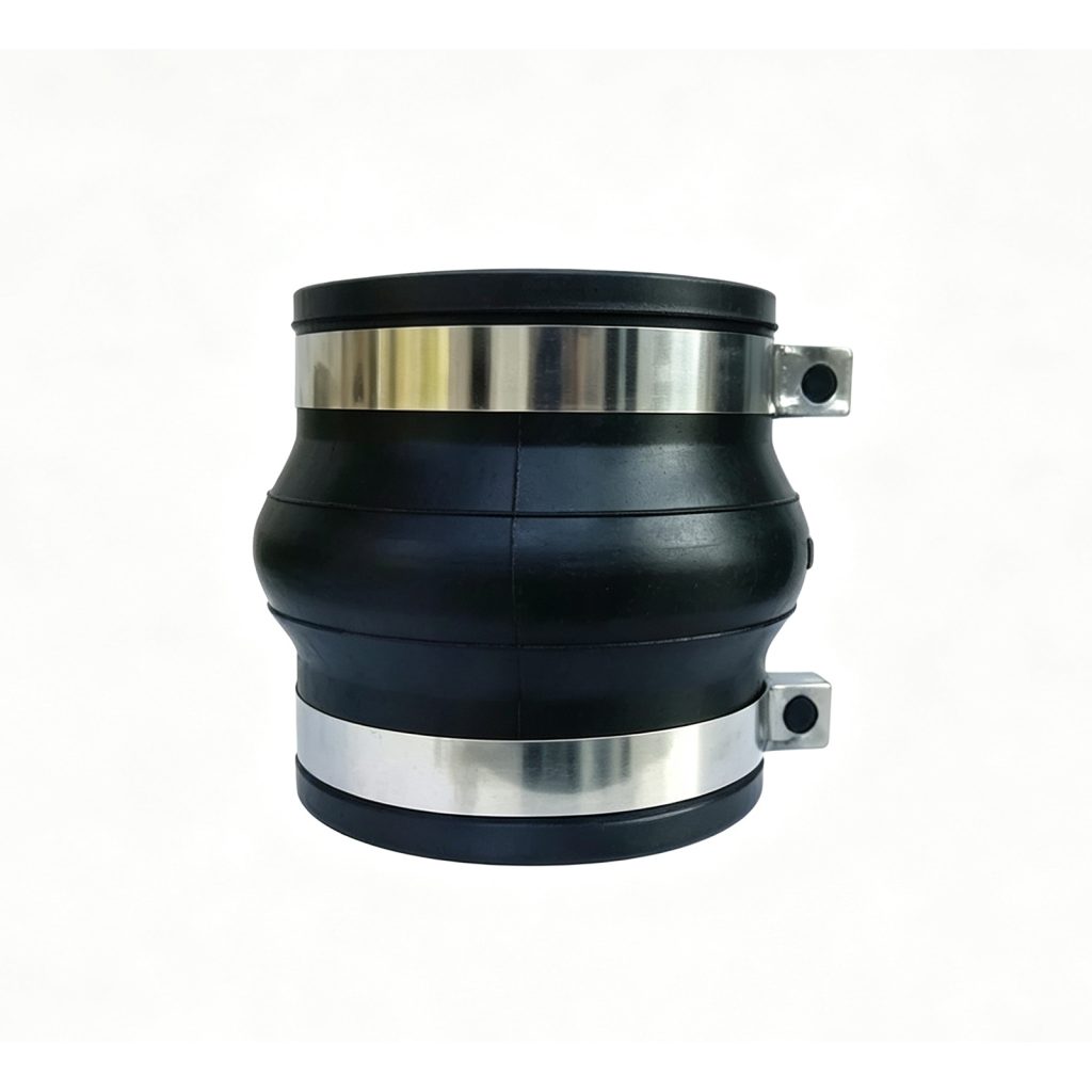
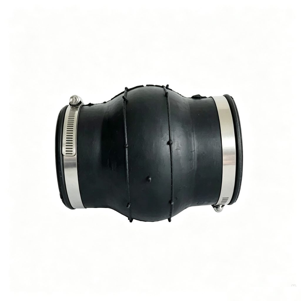
The JGD (KXT) Clamp-Type Rubber Expansion Joint provides a flangeless flexible connection by securing the elastomeric ends to prepared pipe ends with external clamps. Mingchao’s catalog documents DN50–DN2000 configurations with axial, lateral and angular movement data, while non-catalog diameter, face-to-face length, rubber and clamp-interface requirements can be manufactured to approved customer or project drawings.
CLAMP CONNECTION · FLANGELESS FLEXIBLE JOINT · CUSTOM ENGINEERING
- Connection
- Clamp / Flangeless
- Catalog Range
- DN50–DN2000
- Movement
- Axial · Lateral · Angular
- Selection
- Pipe OD · Pressure · Medium
- Customization
- Drawing-Based
Project Configuration
Mingchao can customize the product configuration based on the technical information, operating conditions and dimensional data you provide. Final configuration can be reviewed and manufactured to the approved project drawing.
JGD (KXT) Clamp-Type Rubber Expansion Joint — Overview
The JGD (KXT) Clamp-Type Rubber Expansion Joint provides a flangeless flexible connection by securing the elastomeric ends to prepared pipe ends with external clamps. Mingchao’s catalog documents DN50–DN2000 configurations with axial, lateral and angular movement data, while non-catalog diameter, face-to-face length, rubber and clamp-interface requirements can be manufactured to approved customer or project drawings.
What is a clamp-type rubber expansion joint? It is a flexible rubber connector whose prepared ends are retained by external clamps instead of conventional mating flange pairs.
How the Clamp Connection Works
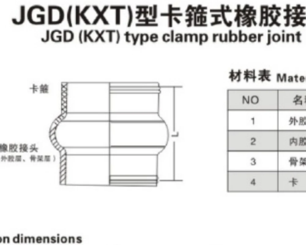
The clamp bands compress the reinforced rubber end sections around compatible prepared pipe ends. Pipe outside diameter, end profile, engagement length and clamp geometry must be confirmed together before manufacture.
Does it require conventional mating flanges? No; this catalog configuration uses clamp bands, but the pipe-end interface must be prepared for the approved clamp arrangement.
Clamp-Type vs. Flanged Rubber Expansion Joint
Unlike a conventional flanged rubber expansion joint, JGD (KXT) clamp configuration does not use two large bolt-hole flange pairs. The clamp interface can simplify a compatible prepared-end connection, but it is not interchangeable with a flanged joint without reviewing pipe ends, pressure, restraint and installation geometry.
Unified Specifications — DN50 to DN2000
Published catalog rows are combined with the engineering selection fields below. DN / NPS — Catalog value where listed; custom geometry to approved drawingPipe OD / Prepared End OD — Project-specific / approved drawingFace-to-Face L — Catalog value where listed; custom geometry to approved drawingAxial Extension — Catalog value where listed; custom geometry to approved drawingAxial Compression — Catalog value where listed; custom geometry to approved drawingLateral Movement — Catalog value where listed; custom geometry to approved drawingAngular Movement — Catalog value where listed; custom geometry to approved drawingClamp Type — Project-specific / approved drawingClamp Material — Project-specific / approved drawingRequired Pipe-End Geometry — Project-specific / approved drawingInsertion / Engagement Requirement — Project-specific / approved drawingRubber Compound — Project-specific / approved drawingReinforcement — Project-specific / approved drawingWorking Pressure — Factory confirmation requiredOperating Temperature — Factory confirmation requiredMedium — Project-specific / approved drawingVacuum Requirement — Factory confirmation requiredInstallation Interface — Project-specific / approved drawingCustomer Drawing — Project-specific / approved drawingCustom Configuration — Project-specific / approved drawing
| DN | NPS | Face-to-Face L (mm) | Axial Extension (mm) | Axial Compression (mm) | Lateral Movement (mm) | Angular Movement (deg) |
|---|---|---|---|---|---|---|
| 50 | 2 | 180 | 7 | 10 | 10 | 15 |
| 65 | 2.5 | 180 | 7 | 13 | 11 | 15 |
| 80 | 3 | 180 | 8 | 15 | 12 | 15 |
| 100 | 4 | 180 | 10 | 19 | 13 | 15 |
| 125 | 5 | 180 | 12 | 19 | 13 | 15 |
| 150 | 6 | 180 | 12 | 20 | 14 | 15 |
| 200 | 8 | 200 | 16 | 25 | 22 | 15 |
| 250 | 10 | 200 | 16 | 25 | 22 | 15 |
| 300 | 12 | 200 | 16 | 25 | 22 | 15 |
| 350 | 14 | 200 | 16 | 25 | 22 | 15 |
| 400 | 16 | 200 | 16 | 25 | 22 | 15 |
| 450 | 18 | 200 | 16 | 25 | 22 | 15 |
| 500 | 20 | 200 | 16 | 25 | 22 | 15 |
| 600 | 24 | 200 | 16 | 25 | 22 | 15 |
| 700 | 28 | 200 | 16 | 25 | 22 | 10 |
| 800 | 32 | 200 | 16 | 25 | 22 | 10 |
| 900 | 36 | 200 | 16 | 25 | 22 | 10 |
| 1000 | 40 | 200 | 18 | 25 | 22 | 10 |
| 1200 | 48 | 200 | 18 | 25 | 24 | 10 |
| 1400 | 56 | 200 | 20 | 26 | 24 | 10 |
| 1600 | 64 | 200 | 25 | 26 | 26 | 10 |
| 1800 | 72 | 200 | 20 | 26 | 26 | 10 |
| 2000 | 80 | 200 | 20 | 26 | 26 | 10 |
Catalog movement values are individual references. Non-catalog geometry is custom to approved drawing; performance requires factory confirmation.
Pipe OD & Clamp Interface Requirements
How should pipe OD be specified? Provide actual prepared-end outside diameter, surface/profile details, intended insertion or engagement length and a drawing of the mating pipe end. Nominal DN alone does not define the clamp interface.
Axial, Lateral & Angular Movement
Catalog movement values are individual size references. Maximum axial, lateral and angular values must not be assumed to occur simultaneously; combined requirements need project review.
Rubber Body, Reinforcement & Clamp Materials
The catalog identifies IIR, CR, EPDM, NR and NBR for inner and outer rubber layers, Nylon reinforcement, and Q235 / 304 / 316L clamp options. Final compound and clamp material depend on medium, temperature, pressure, environment and drawing.
Pressure, Temperature, Medium & Vacuum Selection
Working pressure, temperature, medium and vacuum capability are configuration-dependent. The clamp connection and rubber body must be reviewed as a complete assembly. Is working pressure universal? No.
Custom Diameter, Length & Clamp Geometry
Catalog reference range is DN50–DN2000; it is not a manufacturing maximum. Non-catalog diameter, face-to-face length, rubber compound and clamp-interface geometry can be manufactured to approved customer or project drawings. Can non-catalog sizes be made? Yes, drawing-based.
Installation, Pipe Preparation & Clamp Tightening
- Confirm actual pipe OD and prepared-end geometry.
- Verify engagement length and clamp position.
- Align piping without forcing or twisting the rubber body.
- Support piping and equipment independently.
- Tighten clamps progressively to the project-approved procedure.
- Do not assume a universal clamp torque; obtain factory/project confirmation.
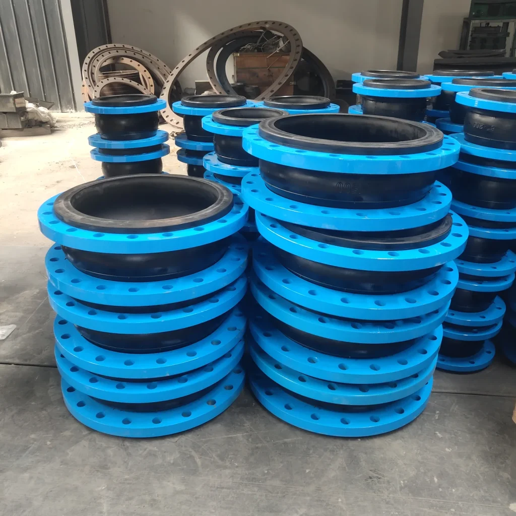
Applications in Water, HVAC & Industrial Piping
Applicable project contexts include water systems, HVAC and district cooling, industrial utilities and large-diameter prepared-end piping where a clamp connection is specified. Suitability depends on pressure, temperature, medium, pipe-end geometry and restraint design.
Project RFQ
Send Pipe OD, DN & Working Conditions. Provide DN/NPS, actual pipe OD, prepared-end drawing, face-to-face length, pressure, temperature, medium, vacuum condition, movement, clamp material, quantity and destination.
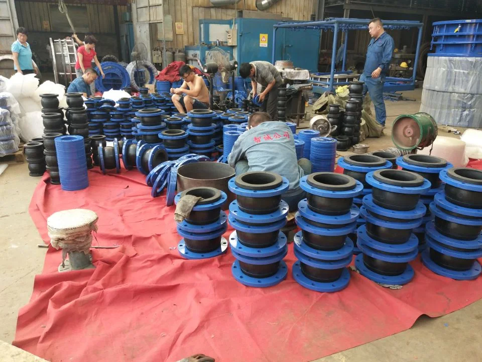
Product Photos
Technical Datasheet
JGD (KXT) Clamp-Type Rubber Expansion Joint
Technical Datasheet · PDF