
Metal Expansion Joints & Compensators
JDH Large Tie-Rod Lateral Corrugated Expansion Joint
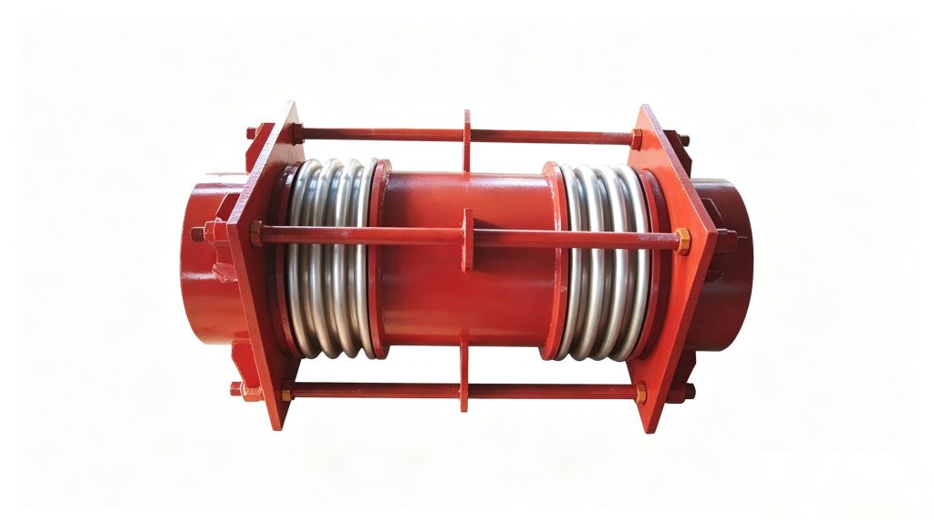
The JDH is Mingchao’s tied-universal metal bellows expansion joint for substantial lateral movement in industrial piping. Two bellows are separated by a center spool, while full-length tie rods restrain internal-pressure thrust across the assembly. Mingchao catalog configurations cover DN100–DN300 with pressure levels from 0.25 to 2.5 MPa.
Tied Universal Expansion Joint
- Model
- JDH
- Industry Type
- Tied Universal Expansion Joint
- Primary Movement
- Lateral
- Size Range
- DN100–DN300
- Pressure Levels
- 0.25 / 0.6 / 1.0 / 1.6 / 2.5 MPa
- Construction
- Two Bellows + Center Spool + Full Tie Rods
- Connection
- Pipe-End / Welded
- Standard
- GB/T 12777-2019
Engineering SelectionConfirm movement plane, piping geometry, pressure, temperature and support conditions against the approved drawing.
Project Configuration
Mingchao can customize the product configuration based on the technical information, operating conditions and dimensional data you provide. Final configuration can be reviewed and manufactured to the approved project drawing.
JDH Large Tie-Rod Lateral Expansion Joint Overview
The JDH is designed for piping systems that require substantial lateral movement within a controlled installation length. Unlike a single axial bellows joint, the JDH uses two bellows separated by a center spool so that the bellows can work as a pair while the assembly shifts laterally.
Mingchao’s catalog configuration uses full-length tie rods across the assembly. These rods form part of the pressure-thrust restraint system and distinguish the JDH from an unrestrained universal expansion joint.
The product should therefore be selected as a lateral-movement solution rather than as a general axial compensator.
How the Tied Universal Configuration Accommodates Lateral Movement
Lateral displacement is produced through controlled angular deflection of the two bellows. As the bellows rotate in opposite directions, the center spool translates sideways and the two pipe ends remain substantially parallel.
The amount of lateral displacement available from a tied-universal design depends on the bellows design, the distance between the bellows, the center-spool length and the required operating conditions.
For JDH selection, use the verified Mingchao technical table as the preliminary dimensional reference and confirm the final movement requirement against the project piping layout.
Two Bellows, Center Spool & Full Tie-Rod Construction
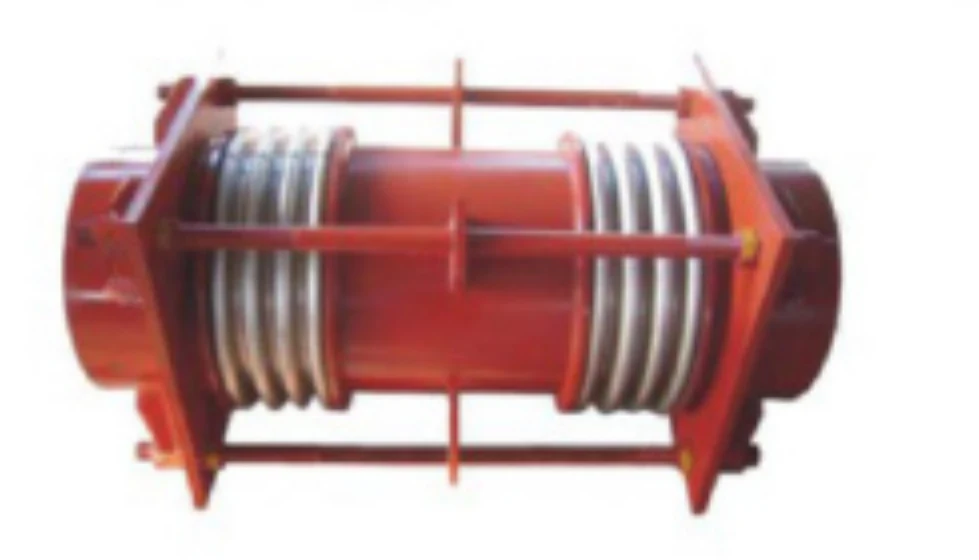
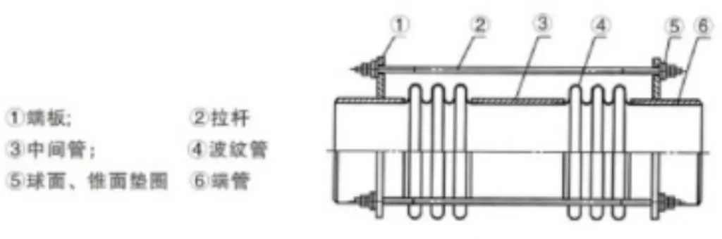
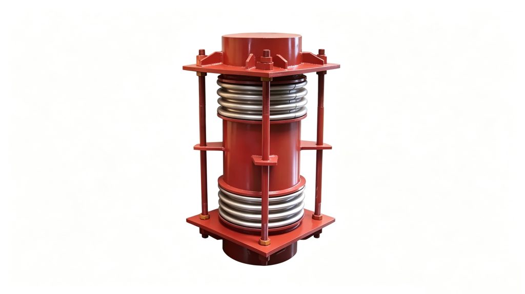
The source-confirmed JDH construction consists of two metal bellows, an intermediate center spool, pipe-end connections and full-length tie rods.
The paired-bellows arrangement provides the geometry required for substantial lateral movement. The center spool separates the two flexible elements, while the tie-rod system connects the ends of the assembly and restrains internal-pressure thrust.
Exact bellows alloy, center-spool material and tie-rod hardware grades are project or factory-confirmation items and must not be presented as universal JDH values until documented.
How the JDH Tie Rods Restrain Pressure Thrust
Internal pressure generates an axial pressure-thrust load in a bellows expansion joint. In the JDH tied arrangement, the full tie-rod hardware is intended to contain this pressure thrust within the expansion-joint assembly.
This reduces the pressure-thrust duty that an unrestrained bellows arrangement would otherwise transfer to external main anchors. It does not remove the need for proper piping engineering.
Guides, supports, spring forces, friction, pipe weight, equipment loads and any required anchors must still be evaluated for the actual piping system.
Technical Data — Lateral Movement & Dimensions
The following data is taken from Mingchao Catalog printed page 30 and is intended for preliminary product selection. Lateral movement and stiffness values vary by nominal diameter, pressure level and overall configuration.
| DN | Wave Number | Pressure (MPa) | 1200 mm — Movement / Stiffness | 1500 mm — Movement / Stiffness | 2000 mm — Movement / Stiffness | 2500 mm — Movement / Stiffness | 3000 mm — Movement / Stiffness | Maximum OD (mm) |
|---|---|---|---|---|---|---|---|---|
| 100 | 4+4 | 0.25 | 177 / 2.2 | 243 / 1.2 | 354 / 0.6 | 465 / 0.3 | 310 | |
| 100 | 4+4 | 0.6 | 177 / 2.2 | 243 / 1.2 | 341 / 0.6 | 447 / 0.3 | 310 | |
| 100 | 4+4 | 1.0 | 163 / 2.2 | 243 / 1.2 | 325 / 0.6 | 427 / 0.3 | 310 | |
| 100 | 4+4 | 1.6 | 91 / 4 | 127 / 2 | 187 / 1 | 247 / 0.6 | 310 | |
| 100 | 4+4 | 2.5 | 94 / 8 | 132 / 5 | 194 / 2 | 256 / 1 | 310 | |
| 125 | 4+4 | 0.25 | 181 / 2.8 | 251 / 1.5 | 369 / 0.7 | 487 / 0.4 | 360 | |
| 125 | 4+4 | 0.6 | 172 / 2.8 | 239 / 1.5 | 351 / 0.7 | 463 / 0.4 | 360 | |
| 125 | 4+4 | 1.0 | 161 / 2.8 | 224 / 1.5 | 330 / 0.7 | 435 / 0.4 | 360 | |
| 125 | 4+4 | 1.6 | 99 / 11 | 140 / 6 | 209 / 3 | 277 / 2 | 360 | |
| 125 | 4+4 | 2.5 | 94 / 11 | 113 / 6 | 197 / 3 | 262 / 2 | 360 | |
| 150 | 4+4 | 0.25 | 199 / 6 | 278 / 3.2 | 410 / 1.6 | 542 / 1.0 | 410 | |
| 150 | 4+4 | 0.6 | 186 / 6 | 259 / 3.2 | 382 / 1.6 | 506 / 1.0 | 410 | |
| 150 | 4+4 | 1.0 | 122 / 10 | 170 / 6 | 251 / 3 | 332 / 2 | 410 | |
| 150 | 4+4 | 1.6 | 108 / 12 | 153 / 6 | 230 / 3 | 307 / 2 | 410 | |
| 150 | 4+4 | 2.5 | 82 / 22 | 117 / 12 | 176 / 5 | 410 | ||
| 200 | 4+4 | 0.25 | 155 / 9.4 | 220 / 4.9 | 327 / 2.25 | 435 / 1.4 | 480 | |
| 200 | 4+4 | 0.6 | 138 / 9.4 | 196 / 4.9 | 291 / 2.25 | 388 / 1.0 | 480 | |
| 200 | 4+4 | 1.0 | 101 / 20 | 143 / 11 | 213 / 5 | 283 / 3 | 480 | |
| 200 | 4+4 | 1.6 | 75 / 42 | 108 / 21 | 164 / 10 | 220 / 6 | 480 | |
| 200 | 4+4 | 2.5 | 59 / 69 | 86 / 35 | 130 / 16 | 176 / 9 | 480 | |
| 250 | 4+4 | 0.25 | 164 / 10.2 | 239 / 5.1 | 367 / 2.4 | 494 / 1.5 | 580 | |
| 250 | 4+4 | 0.6 | 128 / 21 | 188 / 10 | 287 / 5 | 387 / 3 | 580 | |
| 250 | 4+4 | 1.0 | 109 / 35 | 159 / 18 | 243 / 8 | 328 / 5 | 580 | |
| 250 | 4+4 | 1.6 | 76 / 68 | 116 / 33 | 182 / 14 | 249 / 8 | 580 | |
| 250 | 4+4 | 2.5 | 64 / 122 | 98 / 58 | 154 / 25 | 210 / 14 | 580 | |
| 300 | 4+4 | 0.25 | 144 / 17.6 | 174 / 8.4 | 287 / 3.7 | 379 / 2 | 660 | |
| 300 | 4+4 | 0.6 | 94 / 50 | 144 / 24 | 313 / 6 | 660 | ||
| 300 | 4+4 | 1.0 | 127 / 39 | 202 / 17 | 277 / 10 | 352 / 6 | 660 | |
| 300 | 4+4 | 1.6 | 169 / 28 | 169 / 28 | 234 / 15 | 299 / 10 | 660 | |
| 300 | 4+4 | 2.5 | 91 / 113 | 148 / 47 | 215 / 26 | 262 / 16 | 660 |
Final selection should be confirmed against the required lateral movement, piping geometry, operating pressure, temperature, medium and project drawing. Confirm blank table fields against the approved project data.
Typical Applications for JDH Tied Universal Expansion Joints
L-shaped piping layouts
Thermal growth creates a defined lateral offset.
Z-shaped piping layouts
Offset geometry creates controlled lateral movement.
Thermal utility piping
Project-specific lateral movement service.
Power-plant piping
Engineered lateral compensation in power piping layouts.
Process piping
Lateral movement after operating-condition review.
Petrochemical piping
Project-specific tied-universal applications.
Refinery utility systems
Defined lateral offset in utility systems.
Equipment-area piping
Equipment-area piping with defined lateral offset.
These are engineering application contexts, not blanket industry approvals. Final suitability depends on the actual pressure, temperature, medium, materials, movement requirement and support arrangement.
How to Select a JDH Lateral Expansion Joint
JDH selection should begin with the required lateral displacement and the piping geometry, not with nominal diameter alone. First define the required lateral movement and movement plane. Then confirm the available installation length and the L-, Z- or other offset geometry that produces the movement.
- Required lateral movement
- Movement direction / plane
- Piping layout — L / Z / other
- Available offset geometry
- Available installation / overall length
- DN / pipe size
- Design pressure
- Operating pressure
- Design temperature
- Operating temperature
- Medium / fluid
- Pipe-end OD / pipe specification
- Connection requirement
- Material requirement if specified
- Anchor arrangement
- Guide arrangement
- Pipe-support arrangement
- Center-spool support condition if known
- Internal liner requirement if relevant
- Flow velocity if relevant
- Required cycles / fatigue requirement if specified
- Testing / NDT requirement
- Inspection / documentation requirement
- Quantity
- Destination
- Piping layout / project drawing
The technical table should be used as a configuration reference rather than as a substitute for project engineering.
JDH vs Axial Bellows Expansion Joints
The JDH should not be selected simply because the piping system contains thermal expansion. The direction in which that thermal movement must be absorbed determines the appropriate expansion-joint type.
JDH is intended primarily for substantial lateral displacement using a paired-bellows tied configuration.
Axial products such as Mingchao’s JDZ, JZW and BW configurations are selected around axial movement along the pipe centerline and use different restraint, anchoring and installation logic.
Anchors, Guides, Supports & Center-Spool Loads
The JDH tie rods restrain internal-pressure thrust across the tied assembly, but they do not replace the complete piping support system.
Pipe weight should be supported independently so the expansion joint is not used as a structural pipe support.
The piping designer should review guides, supports, spring forces, friction, equipment loads and any main or intermediate anchors required by the actual layout.
Longer or heavier center-spool configurations may also require project-specific support review. Do not publish a universal center-spool support limit until Mingchao provides verified engineering data.
Installation, Alignment & Tie-Rod Protection
Install the JDH at the approved installed length and in the intended lateral-movement plane.
Alignment
Do not use the expansion joint to pull severely misaligned pipework into position.
Pipe Weight
Support pipe weight independently and maintain the specified piping alignment.
Torsion
Do not twist the bellows or introduce torsion during installation.
Tie-Rod Hardware
Do not loosen, tighten, relocate or otherwise adjust the tie-rod hardware unless the approved project drawing specifically requires it.
Protection
Protect the bellows and tie-rod hardware from impact, welding spatter and construction damage.
Pre-Commissioning
Before commissioning or pressure testing, confirm that the piping supports, guides and anchor arrangement correspond to the approved system design.
JDH Product Image, Structural Drawing & Engineering Reference
Use the Mingchao JDH product photograph and structural drawing from Catalog page 30 to identify the paired bellows, center spool, tie rods and pipe-end configuration.
Product Photos
Technical Datasheet
JDH Large Tie-Rod Lateral Corrugated Expansion Joint
Technical Datasheet · PDF