
Metal Expansion Joints & Compensators
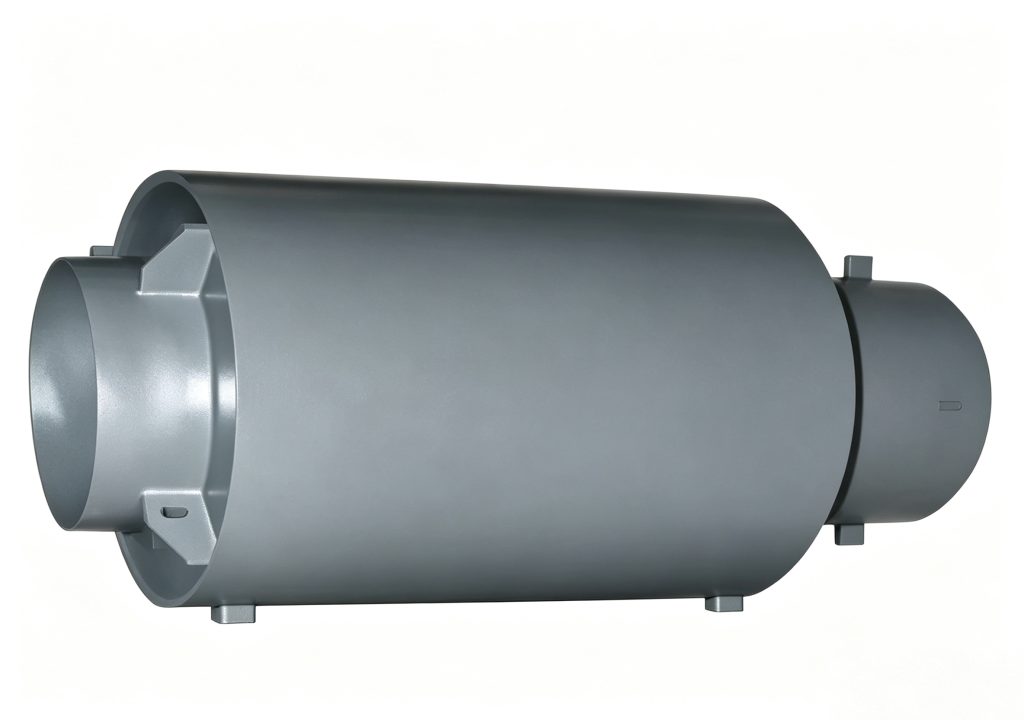
BW Unrestrained Corrugated Expansion Joint
The Mingchao BW Unrestrained Corrugated Expansion Joint is an axial metal bellows compensator with integrated directional protection and guiding components. Catalog configurations cover DN50–DN1000 and pressure levels of 1.0, 1.6 and 2.5 MPa. Because the BW is unrestrained, pressure thrust, anchors, guides and piping alignment must be addressed by the piping-system design.
Also searched as an unrestrained expansion joint, unrestrained axial expansion joint, untied axial expansion joint or unrestrained bellows expansion joint.
- Model
- BW
- Size Range
- DN50–DN1000
- Primary Movement
- Axial
- Pressure Levels
- 1.0 / 1.6 / 2.5 MPa
- Construction
- Bellows + Directional Protection / Guide Components
- Connection
- Pipe-End / Nozzle
- Catalog Configurations
- Multiple Wave Numbers and Lengths
- Standard
- GB/T 12777-2019
Project ConfigurationWave number, length, material and connection details are reviewed against confirmed project requirements.
Project Configuration
Mingchao can customize the product configuration based on the technical information, operating conditions and dimensional data you provide. Final configuration can be reviewed and manufactured to the approved project drawing.
BW Unrestrained Corrugated Expansion Joint Overview
The Mingchao BW Unrestrained Corrugated Expansion Joint is designed primarily for axial thermal movement in industrial and thermal piping.
Unlike a pressure-balanced or tied expansion joint, the BW does not restrain pipeline pressure thrust. Main anchors, directional guides and independent pipe support remain essential parts of the piping-system design.
The current Mingchao catalog documents DN50–DN1000 configurations with multiple wave numbers, installed lengths and 1.0, 1.6 and 2.5 MPa pressure levels.
What “Unrestrained” Means in the BW Design
In the BW design, “unrestrained” means the expansion joint does not provide a structural restraint that removes pipeline pressure thrust. The piping system must therefore include correctly designed anchors and guides.
The Mingchao BW is not merely a bare bellows. Its catalog drawing shows integrated directional protection, guiding and liner components around the bellows assembly.
| Specification | Confirmed Data |
|---|---|
| Product Type | BW Unrestrained Corrugated Expansion Joint |
| Model | BW |
| Size Range | DN50–DN1000 |
| Pressure Levels | 1.0 / 1.6 / 2.5 MPa |
| Primary Movement | Axial |
| Construction | Bellows with integrated directional protection and guiding components |
| Connection | Pipe-End / nozzle configuration |
| Standard | GB/T 12777-2019 |
BW Construction & Guiding Arrangement
The published BW arrangement includes a working connection pipe, main directional flange, directional protective sleeve, bellows, flow liner, guide sleeve, secondary directional flange, inner liner, limit ring and intermediate flange.
These parts guide and protect the bellows assembly, but they do not make the product pressure-balanced and do not replace required system anchors.
Technical Data — Movement & Dimensions
The table publishes only p27 fields whose headings and values are unambiguous: nominal diameter, wave number, effective bellows area, nozzle size and total length.
| DN | Wave Number | Effective Bellows Area (cm²) | Nozzle Size (mm) | Total Length (mm) |
|---|---|---|---|---|
| 50 | 8 | 50 | Ø57x3.5 | 350 |
| 50 | 16 | 50 | Ø57x3.5 | 480 |
| 50 | 32 | 50 | Ø57x3.5 | 620 |
| 65 | 8 | 55 | Ø73x4 | 440 |
| 65 | 12 | 55 | Ø73x4 | 520 |
| 65 | 24 | 55 | Ø73x4 | 600 |
| 80 | 8 | 81 | Ø89x4 | 470 |
| 80 | 10 | 81 | Ø89x4 | 510 |
| 80 | 20 | 81 | Ø89x4 | 680 |
| 100 | 8 | 121 | Ø108x4 | 500 |
| 100 | 10 | 121 | Ø108x4 | 540 |
| 100 | 20 | 121 | Ø108x4 | 700 |
| 125 | 8 | 180 | Ø133x4 | 540 |
| 150 | 8 | 257 | Ø219x4.5 | 550 |
| 200 | 8 | 479 | Ø219x6 | 600 |
| 250 | 8 | 769 | Ø273x8 | 640 |
| 300 | 8 | 1105 | Ø325x8 | 660 |
| 350 | 6 | 1307 | Ø377x10 | 665 |
| 400 | 6 | 1611 | Ø426x10 | 665 |
| 450 | 6 | 1972 | Ø478x10 | 720 |
| 500 | 6 | 2445 | Ø529x10 | 720 |
| 600 | 6 | 3534 | Ø630x10 | 780 |
| 700 | 6 | 4717 | Ø720x10 | 850 |
| 800 | 4 | 5822 | Ø820x10 | 750 |
| 900 | 4 | 7620 | Ø920x10 | 750 |
| 1000 | 4 | 9043 | Ø1020x10 | 780 |
Confirm the applicable pressure-level values for the selected configuration with the factory.
Pressure Thrust, Anchors & Guides
- Pressure thrust must be considered in anchor design.
- Pipe guides must maintain the intended axial movement path.
- Connected piping and equipment must be independently supported.
- Do not use the BW to correct severe misalignment.
- Do not treat the integrated guide arrangement as a replacement for system piping design.
Applications in Steam, Utility & Industrial Piping
Steam & Condensate Piping
Axial thermal movement where the selected configuration is suitable.
Hot-Water Utilities
Axial movement compensation in thermal utility piping.
Industrial Process Piping
Unrestrained bellows compensation within approved operating conditions.
Power & Utility Systems
Axial movement in utility piping with engineered anchors and guides.
Heating & Cooling Piping
Thermal expansion compensation in long straight piping sections.
Equipment-Area Piping
Movement accommodation where piping loads and equipment connections are reviewed.
Suitability depends on the confirmed medium, pressure, temperature, movement and piping layout.
How to Select a BW Expansion Joint
Provide:
- DN / pipe size
- Required axial movement
- Design pressure
- Normal working pressure
- Operating temperature
- Process medium
- Required installed length
- Required end connection
- Pipe outside diameter / specification
- Main anchor arrangement
- Directional guide arrangement
- Installation orientation
- Flow direction
- Quantity
- Destination country
- Project drawing
- Testing requirements
- Documentation requirements
Confirm all operating and piping-layout data before production.
BW vs. JZW Externally Pressurized Expansion Joint
| Point | BW Unrestrained | JZW Externally Pressurized |
|---|---|---|
| Pressure arrangement | Conventional BW bellows path | Process pressure acts outside the bellows |
| Primary movement | Axial | Axial, including long-stroke configurations |
| Pressure thrust | Must be resisted by system anchors | Must be resisted by system anchors |
BW vs. JDZ Internal-Pressure Axial Expansion Joint
| Point | BW | JDZ Internal-Pressure Axial |
|---|---|---|
| Structure | Integrated directional protection and guiding arrangement | Conventional internal-pressure axial configuration |
| Selection | Use exact BW dimensions and guide arrangement | Use JDZ product-specific movement data |
| Interchangeability | Not interchangeable without piping-system review | |
Installation, Alignment & Flow Direction
Follow the approved BW drawing and piping-system design.
Identity
Verify BW model, DN, pressure level and length.
Flow
Confirm the indicated medium flow direction.
Axial Alignment
Install in the intended axial line.
No Torsion
Do not twist the assembly.
No Forced Misalignment
Do not force the joint into severe piping misalignment.
Anchors
Install required main anchors.
Guides
Install directional guides required by the system design.
Independent Support
Support pipe and equipment independently.
Neutral Length
Confirm installed length before welding or final connection.
Protection
Protect casing, bellows and weld areas during handling.
Hardware
Do not alter limit or transport components without approval.
Testing
Follow the approved pressure/leak-test procedure.
Inspection
Inspect connections, casing and movement components before service.
Real Product Photos, Drawings & Technical References
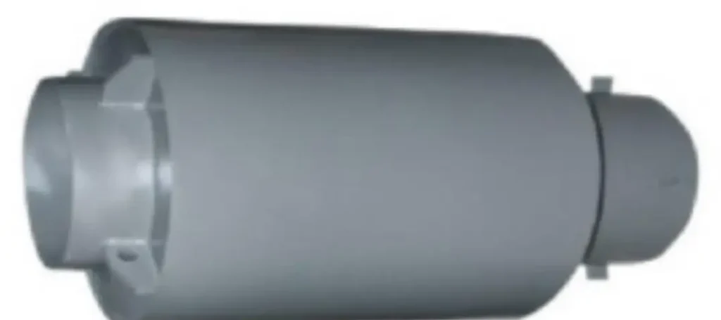
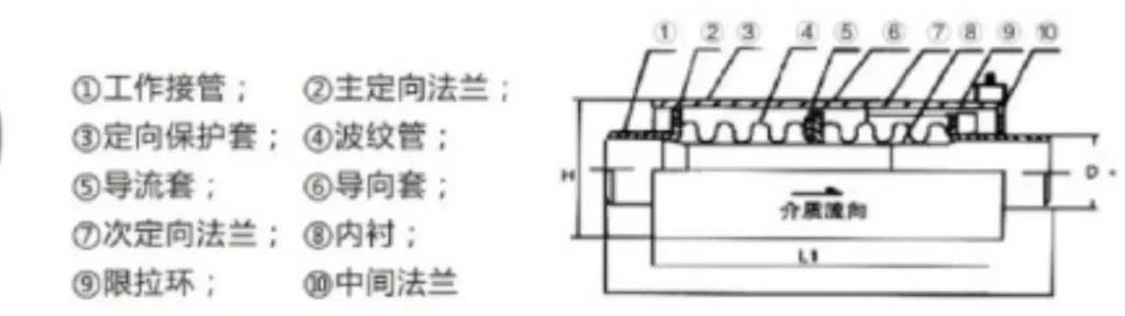
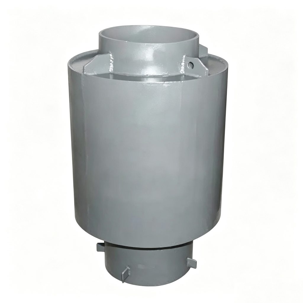
The pressure-level value pairs in the legacy catalog are not republished because their subheader conflicts with the separate total-length field. No inferred movement or stiffness values are presented.
Product Photos
Technical Datasheet
BW Unrestrained Corrugated Expansion Joint
Technical Datasheet · PDF