
On this page
A rubber expansion joint may be listed with axial, lateral and angular movement values. Those separate figures do not, by themselves, show whether the joint can accommodate the movements occurring together in a particular installation.
The assessment starts before the system runs. If the installed distance between flange faces differs from the selected joint’s nominal length, or the flange centres are offset, the joint begins service in a displaced position. Changes during operation must then be assessed from that actual installed condition.
This article sets out a way to record the geometry and operating states. It does not assign a combined-movement rating to a particular product: that conclusion requires the selected assembly’s approved data and a review of the piping arrangement.
Establish the flange datum before calculating movement
Choose one mating flange as the fixed reference, F₁, and describe the position of the second flange, F₂, relative to it. Record the axes and sign convention on the drawing so that a value such as “6 mm lateral” has an unambiguous direction.
For the cold, installed condition, measure or confirm:
- The selected joint’s specified face-to-face length, L₀.
- The distance between the installed mating flange faces, Linstalled.
- Horizontal and vertical displacement between flange centres.
- Any difference in flange-face angle.
- The source of each value: an approved drawing, a field survey or a manufacturer’s product document.
The initial axial displacement is Linstalled − L₀ under the stated sign convention. It is only one part of the installed geometry. Flange-centre offset and face angle need separate entries; one cannot reliably be inferred from another.
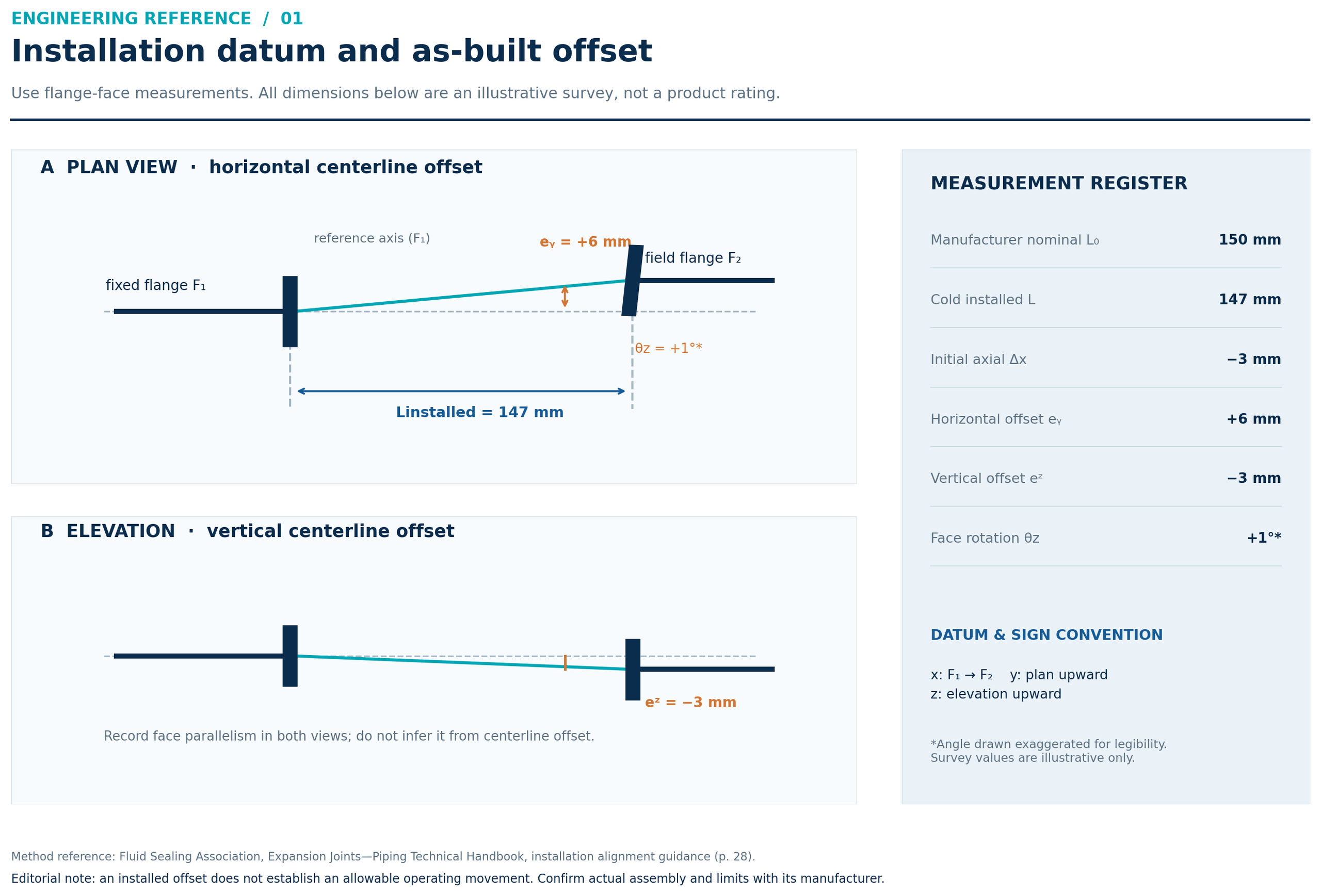
Figure . Orthographic views show where to record installed length, offsets and flange-face angle. The dimensions illustrate a measurement method; they are not Mingchao product limits.
In Figure , the illustrative nominal length is 150 mm and the installed length is 147 mm, giving an initial axial displacement of −3 mm. The horizontal and vertical offsets are recorded separately. These values describe where the flanges are; they do not establish that any proposed joint may safely be installed there.
This distinction matters in replacement work. Measuring an old joint in place does not necessarily reveal its original free length. Nor should a new joint be pulled into a gap simply because its catalogue extension value appears large enough. The Fluid Sealing Association (FSA) installation guidance states that piping misalignment can reduce available rated movement and place additional stress on a joint.
Describe movement as operating states
The next step is to record the positions the flanges occupy during service. A list containing “maximum compression,” “maximum lateral movement” and “maximum temperature” is insufficient if those maxima occur at different times.
Use one row for each condition that the joint must withstand. Depending on the system, these may include the installed cold condition, normal operation, startup, shutdown and the specified test condition. Record pressure and temperature in the same row as movement so that the reviewer knows which demands occur together.
| Condition | Axial position | Horizontal and vertical offset | Flange-face angle | Pressure and temperature | Source |
|---|---|---|---|---|---|
| Cold, installed | Field value | Field value | Field value | As applicable | Installation survey |
| Normal operation | Calculated or measured | Calculated or measured | Calculated or measured | Operating case | Piping calculation or measurement |
| Startup or shutdown | Case-specific value | Case-specific value | Case-specific value | Transient case | System design |
| Specified test | Case-specific value | Case-specific value | Case-specific value | Test condition | Test procedure |
The table is a data collection format, not a statement that every joint is suitable for every listed condition. If a displacement has not been calculated or measured, mark it as unknown. An assumed zero may conceal the controlling case.
The reviewer also needs to know whether each number is expressed relative to the manufacturer’s nominal position, the cold installed position or another defined datum. Mixing these reference positions can produce a reassuring but incorrect movement total.
Separate catalogue movements from concurrent movement
A product table may show individual axial compression, axial extension, lateral movement and angular movement values. These describe movement directions, but they should not be read as permission to reach every listed maximum simultaneously.
The FSA technical handbook provides a method for assessing concurrent movements. In its worked example, a joint with 4 in of rated compression and 1 in of rated lateral movement is subjected to 2 in of compression and 0.75 in of lateral movement at the same time. The corresponding fractions total 0.50 + 0.75 = 1.25, exceeding the handbook example’s criterion and requiring further evaluation. The handbook also specifies how angular movement is treated within that method. Its equation should therefore be read in full, rather than extended casually to a different construction or applied twice to the same deformation.
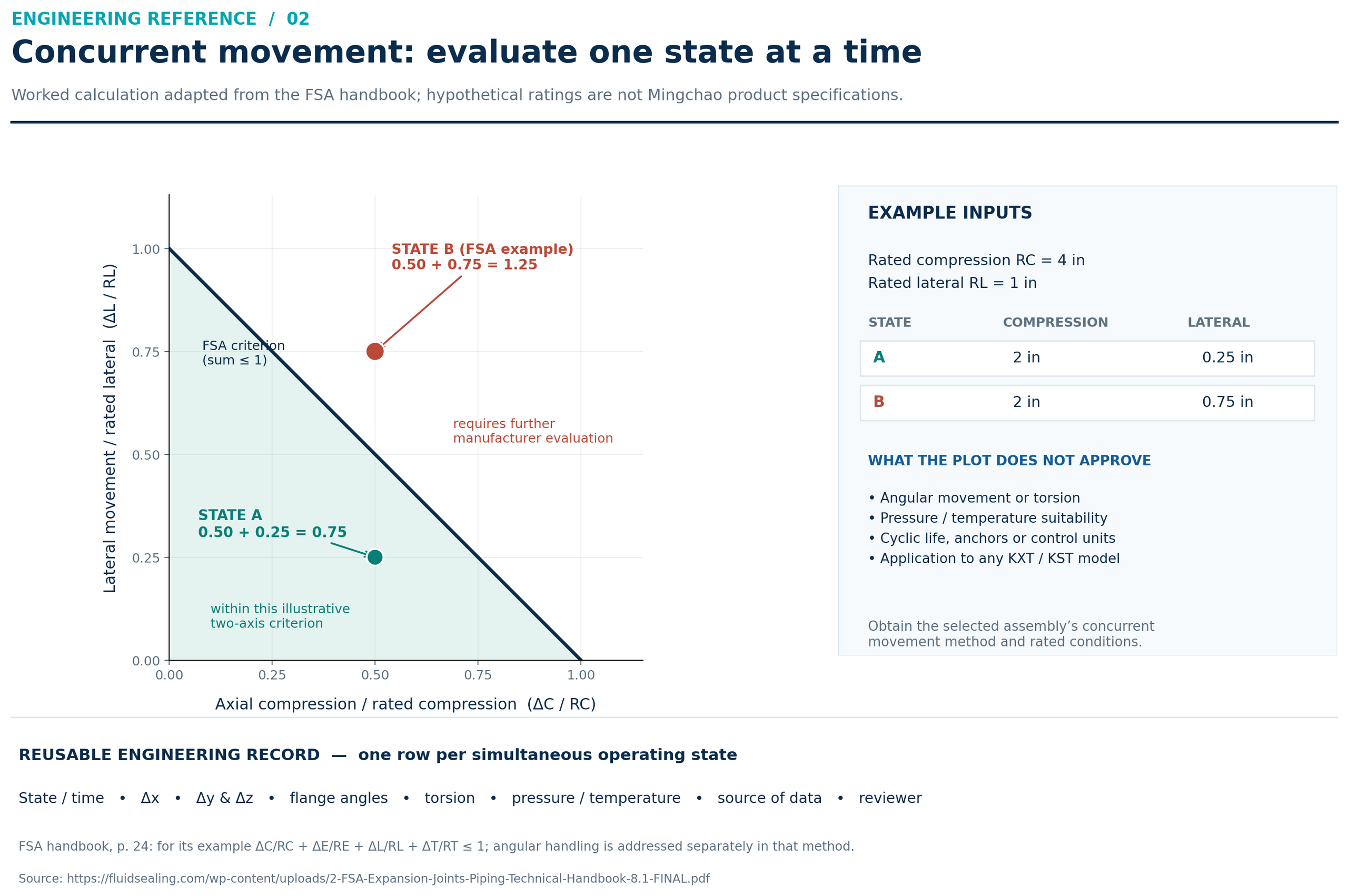
Figure . Two illustrative states are plotted against the FSA example’s two-component criterion. The figure explains the calculation method; its hypothetical ratings do not apply to a Mingchao model.
Figure adds a second, smaller lateral displacement to show why the combination in each state matters. A point falling within the illustrated two-axis calculation is not a product approval. It says nothing on its own about angular movement, twisting, pressure, temperature, cycle life or the suitability of the complete piping system.
Likewise, axial extension and compression may be different states in a service cycle. Do not add unrelated maxima from different states as though they happened at one instant. Do not replace a manufacturer’s combined-movement method with an arbitrary vector magnitude or a calculation borrowed from a different joint.
Account for angle, torsion and restraint separately
Flange-face angle should be recorded even when a drawing provides a lateral offset. Parallel but offset flanges and nonparallel flanges impose different geometry on the joint. Where angular movement occurs together with other movements, the selected manufacturer’s method must determine how it enters the assessment; otherwise the same deformation can be counted incorrectly.
Torsion also needs an explicit check. A permissible torsional movement in a particular published design must not be assumed for another design, and it is not a reason to twist a joint during installation. Mingchao’s published KXT and KST installation guidance cautions against forcing the joint into torsion or using it to correct excessive piping misalignment. Flexible Rubber Joint
Movement capacity is only one part of the system review. Anchors, guides, supports, nearby equipment and any control units determine how displacement reaches the joint. Restraint arrangements can also change which movements remain available. These items should appear on the piping sketch submitted with the movement schedule.
Apply the method to a selected product
Mingchao publishes separate KXT single-sphere and KST double-sphere product information. The selected configuration must be identified by more than its nominal pipe size: length, connection, construction and service conditions all affect what needs to be reviewed. Published individual movement figures must not be combined into an unverified rating for a specific KXT or KST assembly. www.mingchaoft.com
For a technical review, send:
- The proposed or existing joint model, nominal size, connection and selected face-to-face length.
- A dimensioned drawing or field survey identifying both mating flange faces and the cold installed position.
- One movement record for each simultaneous operating state, with its datum and sign convention.
- Normal, design and specified test pressure and temperature; identify vacuum duty where applicable.
- The medium, expected cycling and any relevant startup or shutdown conditions.
- A piping sketch showing anchors, guides, supports, equipment connections and control units.
- The product document and drawing revision used for the proposed selection.
Where the existing pipework is substantially out of alignment, resolve the installation geometry as an engineering issue before treating the expansion joint as the solution. The FSA handbook describes purpose-designed offset joints for certain initial misalignments and recommends supplying complete drawings and specifications for such enquiries. That is a distinct configuration decision, not an assumed capability of a standard joint.
What the review should conclude
A useful approval is specific. It identifies the selected assembly, its installed position, the operating states assessed, the manufacturer’s applicable combined-movement method and any required piping or restraint conditions. If one of those inputs is missing, the result remains an open engineering question rather than a confirmed movement rating.
For project preparation, see Mingchao’s Technical Information & Engineering Resources. For related decisions, read Rubber Expansion Joints for Pump Suction and Discharge: Selection Requirements and Technical Requirements for Rubber Expansion Joint Replacement: Seven Key Checks.
Technical reference
- Fluid Sealing Association, Expansion Joints—Piping Technical Handbook: movement definitions, concurrent-movement example, installation alignment and offset-joint guidance.