On this page
- Pump suction does not always mean vacuum
- A positive-pressure grade does not establish vacuum capability
- Check installed length together with vacuum and movement
- When is an internal support needed?
- Verify installation and the surrounding piping
- Vacuum-service review sheet
- Conclusion
- Technical References and Related Products
A rubber expansion joint on a pump suction line is not necessarily in vacuum service. If the pump has a flooded inlet or receives liquid from a pressurized vessel, pressure at the joint can remain above atmospheric pressure. In another operating state, the internal pressure may fall below the pressure outside the joint. The difference between these cases determines which capability must be verified.
For a vacuum-service rubber expansion joint, the selection question is specific: Can the proposed construction resist the greatest external-to-internal pressure difference at its actual installed length, temperature and movement state? A positive-pressure class, flange designation or description such as “pump suction joint” cannot answer it.
This article focuses on that question. Pump hydraulic performance, net positive suction head and cavitation require their own assessment by the pump and system designers; vacuum suitability of the flexible joint does not establish that the pump suction design is acceptable.
Pump suction does not always mean vacuum
The pressure to specify is the pressure at the joint, across the operating states that matter to the project. A pump inlet can be pressurized during normal operation, approach atmospheric pressure at another duty point, or encounter sub-atmospheric pressure in a different system arrangement. Start-up, priming, draining and shutdown should be reviewed when they can produce a more severe condition than steady operation. Do not assume that each of these conditions occurs on every installation.
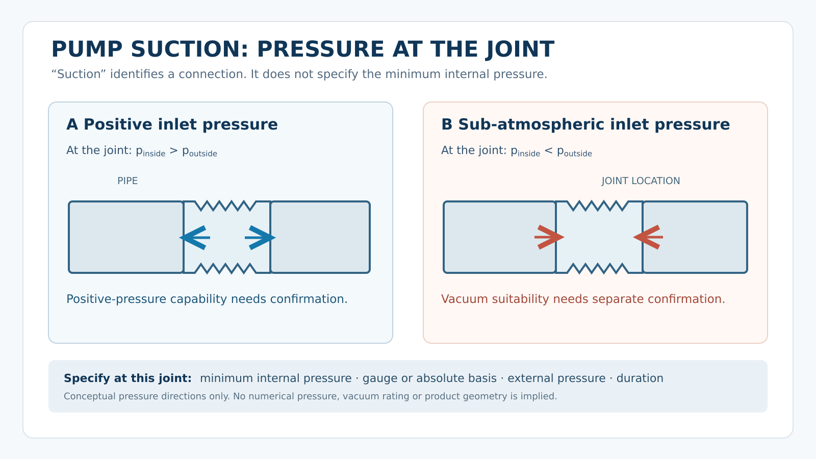
Positive and sub-atmospheric pressure are possible at a pump suction joint. The arrows illustrate pressure direction only; no pressure value or product rating is implied.
Record whether each supplied value is absolute pressure or gauge pressure. A pressure of 0 kPa(g) is approximately local atmospheric pressure, whereas 0 kPa(a) is the theoretical zero of the absolute scale. “Full vacuum” should not replace a measured or specified minimum internal pressure. Local atmospheric pressure may also matter when converting an absolute value into a pressure difference.
The external-to-internal pressure difference is:
Δpᵥ = pₒᵤₜₛᵢdₑ − pᵢₙₛᵢdₑ, when outside pressure exceeds inside pressure.
This expression defines the loading condition; it is not a formula for the allowable vacuum of a rubber joint. The allowable condition comes from the selected manufacturer’s construction and supporting data. Identify how long the minimum pressure lasts, how often it occurs, the temperature at that time and whether a different positive-pressure or test case must also be accommodated.
A positive-pressure grade does not establish vacuum capability
Under positive internal pressure, the pressure difference acts outward on the rubber body. When internal pressure is lower than the surrounding pressure, the body is loaded inward. The construction must retain its required shape and function in the latter condition, including the intended connection integrity and movement capability.
Mingchao lists positive working-pressure options on its vacuum-resistant rubber expansion joint product page. Its product datasheet explicitly states that these pressure grades are not vacuum ratings. It calls for the allowable vacuum to be confirmed for the selected body and support configuration. Therefore, neither a 1.0 MPa positive-pressure option nor a nominal pipe diameter is evidence of a particular allowable negative pressure. Mingchao
Ask for confirmation that identifies the selected joint size, rubber-body construction, any vacuum-support arrangement, installed condition and allowable vacuum at the relevant temperature. If the only available document describes a product family without a configuration-specific vacuum value, record vacuum capability: to be confirmed. Do not silently substitute a rating from a different manufacturer or a similar-looking joint.
Check installed length together with vacuum and movement
Catalogue movement and vacuum information is often conditional on an installation position. A manufacturer may define a neutral face-to-face length at which a published rating applies. The actual cold installed length may differ because of a specified preset, piping geometry or an existing replacement gap. Operating temperature and pipe movement may change that length again.
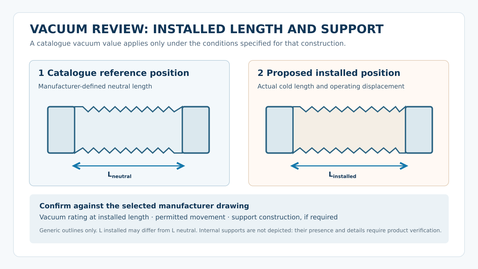
Compare the manufacturer’s neutral reference length with the actual installed and operating positions. The outlines are conceptual; the presence and geometry of an internal support are not asserted.
For the proposed joint, write down the manufacturer’s reference length, the required cold face-to-face length, and the shortest and longest expected operating lengths. Add the required lateral displacement and angular movement, including movements that occur at the same time as the minimum internal pressure. Ask whether the vacuum capability still applies in each relevant position.
This qualification is not theoretical: Proco states for its Style 231 product that its published vacuum rating is based on a neutral installed length without external load, and warns against installing those particular joints extended for vacuum applications. That is a condition on Proco’s product, not a universal installation limit or a Mingchao rating. The transferable lesson is to read and verify the conditions attached to the selected manufacturer’s vacuum data.
If an existing pipe gap requires pulling the joint longer to reach the mating flanges, do not treat that extension as free installation tolerance. Record the gap and obtain an approved configuration or correct the piping arrangement. A vacuum check based on an unextended catalogue joint cannot simply be copied onto an unreviewed extended installation.
When is an internal support needed?
Some vacuum-service constructions use an internal support element or another body design to help resist inward deformation. Such hardware is not a universal requirement for every vacuum condition. Whether it is needed depends on the pressure difference, size, body construction, installed length, temperature and movement requirements of the actual joint.
Mingchao’s vacuum-service datasheet says that an internal vacuum-support configuration can be used and depicts a schematic support element. It also says final support geometry and operating limits follow the approved drawing. Accordingly, do not assume that every Mingchao vacuum-resistant joint contains the depicted element, or that a particular support ring can be inserted into an existing joint without redesign. mingchaoft.com
If support is proposed, the technical review should establish its location and retention method on the approved drawing; its compatibility with the fluid, flow direction, solids and cleaning method; and its effect on axial, lateral and angular movement. The supplier should also confirm how the complete assembly is inspected and installed. These are review questions, not a recommendation to add a loose ring or modify the rubber body in the field.
Figure 6 intentionally leaves the internal structure blank. Replace it with an annotated Mingchao section drawing or verified product photograph only after company technical staff confirm that the image represents the configuration described in the article.
Verify installation and the surrounding piping
Vacuum capability of the joint is one part of the installation assessment. Connected piping needs its own supports so pipe and fluid weight are not carried by the rubber body. Confirm flange alignment and the approved face-to-face dimension; do not twist the joint or use it to pull misaligned flanges into place. Anchors, guides and any restraint hardware should be reviewed against the piping design, including pressure cases that differ from the minimum-pressure condition.
For pump suction, separately review the suction piping and pump manufacturer’s requirements. A joint suitable for a specified vacuum does not prove that the pump will operate without cavitation, nor does it determine the allowable nozzle loads. Similarly, an internal support that helps maintain the joint’s shape does not replace external pipe supports or a system restraint design.
The Fluid Sealing Association’s installation specification calls for pressure/vacuum, temperature and movement to be checked against system requirements and for anchors, supports and guides to be reviewed. These checks belong to the complete piping system, even when the joint itself has been selected for vacuum service.
Vacuum-service review sheet
Use the same pressure reference and units throughout the supplier enquiry. For missing inputs, write to be confirmed rather than assigning a typical value.
| Review item | Information the engineer or supplier needs |
|---|---|
| Location and duty | Pump suction or other vacuum location; operating modes that may produce minimum internal pressure. |
| Minimum pressure | Lowest pressure at the joint; value and units; absolute or gauge reference; outside pressure if relevant. |
| Exposure | Duration and frequency of the minimum-pressure condition; temperature during that condition. |
| Other pressure cases | Positive operating/design pressure, transient conditions and specified test condition, assessed separately. |
| Joint identity | Proposed manufacturer, construction, size and documented vacuum capability for that exact configuration. |
| Installation geometry | Manufacturer-defined neutral length; required cold installed length; flange details and alignment. |
| Operating movement | Axial extension and compression, lateral displacement and angular rotation; which occur simultaneously with vacuum. |
| Internal construction | Whether a support is present or proposed; approved geometry, retention and effect on flow, cleaning and movement. |
| System boundary | Pipe supports, anchors, guides, equipment connections and allowable nozzle loads where applicable. |
| Approval evidence | Configuration-specific product document, approved drawing and installation instructions; unresolved items assigned for confirmation. |
The completed sheet is useful for a new project and for replacing a joint already installed on a suction line. In a replacement, photograph the old joint and record its actual face-to-face length and flange arrangement, but do not assume its appearance establishes its original vacuum capability.
Conclusion
Vacuum selection begins with the lowest internal pressure at the joint and the corresponding outside pressure. The proposed rubber expansion joint then needs a confirmed vacuum capability at its actual installed length and operating movement, with any support construction identified on an approved drawing. Positive-pressure class, pump location and visual similarity cannot fill gaps in those three checks.
Mingchao can review the supplied pressure cases, installation dimensions and drawings for a suitable vacuum-service configuration. Final product values and system acceptance should be confirmed for the selected construction and the project’s approved piping design.
Technical References and Related Products
Mingchao product and project information
- Vacuum-Resistant Rubber Expansion Joint — product configuration and conditions to supply for selection.
- Vacuum-Resistant Rubber Expansion Joint — Technical Datasheet (PDF) — product-specific document distinguishing positive-pressure grades from configuration-dependent vacuum capability.
- Technical Information & Project Requirements — technical information for a project review.
Related Mingchao article
- Rubber Expansion Joints for Pump Suction and Discharge: Selection Requirements — the broader pump-connection review, including suction and discharge differences.