
On this page
- Calculate the thrust at the joint, not from its nominal size
- Draw the load path before choosing the rods
- A limit rod changes function when its stop engages
- Check movement and pressure as one operating envelope
- What changes at a pump connection?
- Information needed to review an anchored or tied proposal
- Conclusion
- Technical References and Related Products
A rubber expansion joint permits movement between two pipe ends, but flexibility does not remove the force produced by internal pressure. The piping design must show where that force goes. At a pump, the distinction matters: a joint may accommodate an intended displacement while the same installation imposes an unacceptable force on a pump nozzle.
Our previous article on rubber expansion joints for pump suction and discharge introduced pressure thrust as a selection check. This article takes the next step: compare the load path through pipe anchors with the load path through an engineered rod assembly, and determine what happens to axial movement in each case.
Calculate the thrust at the joint, not from its nominal size
For a straight, unrestrained joint, the pressure-thrust component can be expressed as:
Fₚ = Δp × Aₑ
Here Δp is the pressure inside the joint minus the pressure outside it, and Aₑ is the effective pressure area of the selected joint construction. Use consistent units: MPa multiplied by mm² yields newtons. The pressure difference here is not pump discharge pressure minus pump suction pressure.
The effective area should come from the joint manufacturer. Nominal pipe size, rubber bore diameter and bolt-circle diameter do not automatically give the correct value. Establish the applicable normal, maximum, surge and test pressure cases, including their temperatures and durations. A thrust calculation alone is not a joint rating, a rod rating or a pump-nozzle-load calculation.
Pressure also produces a tendency for the joint to change length. The restraint layout determines whether that tendency is resisted by pipe anchors, by a suitably engineered assembly connecting the two ends, or, in a poorly defined system, by equipment and piping that were never intended to take it.
Draw the load path before choosing the rods
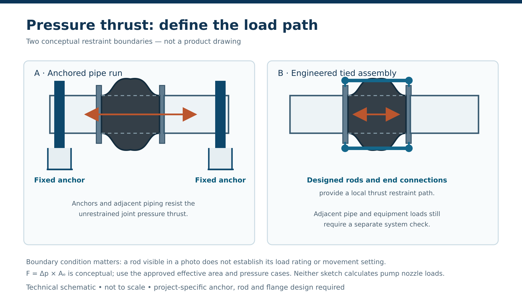
Caption: Two possible pressure-thrust load paths: an engineered anchor arrangement and an engineered tied assembly. Schematic only; not an approved installation detail or product rating.
In an anchored arrangement, the designer establishes a restrained pipe section and sizes the anchors, guides, supports and their attachments for the applicable loads. The rubber joint can then be assessed for the permitted axial, lateral and angular displacement within that section. An anchor is an engineered load-bearing point, not merely a pipe support or a clamp placed nearby. The force and moment reaching any connected pump or valve must still be checked.
In an engineered tied arrangement, a specified mechanical load path connects the joint ends and is designed to react the pressure thrust. This can reduce the thrust passed into the surrounding piping through that joint, but the rods, nuts, plates, flanges, bolts and their attachments must all be reviewed for the design case. The permitted movement depends on how this particular assembly is detailed. A drawing showing rods is insufficient evidence of either full restraint or a particular movement allowance.
| Question on the assembly drawing | Why it matters |
|---|---|
| Where does pressure thrust act and where is it reacted? | Identifies whether anchors, rods, equipment or another structure take the axial load. |
| Are the nuts bearing against the plates at the installed length? | Determines whether a rod path is engaged immediately or only after a specified gap closes. |
| Which movements are permitted together? | Prevents applying separate catalogue maxima as if they were simultaneous. |
| What carries pipe weight and other external loads? | Keeps weight, thermal loads and equipment loads out of an assumed joint-only calculation. |
There is no universal rule that fitting rods eliminates the need to review anchors. Rods may limit extension, restrain both directions, or perform another defined function. The design of the whole piping system, including bends and branches outside the illustrated section, remains the responsibility of the piping engineer.
A limit rod changes function when its stop engages
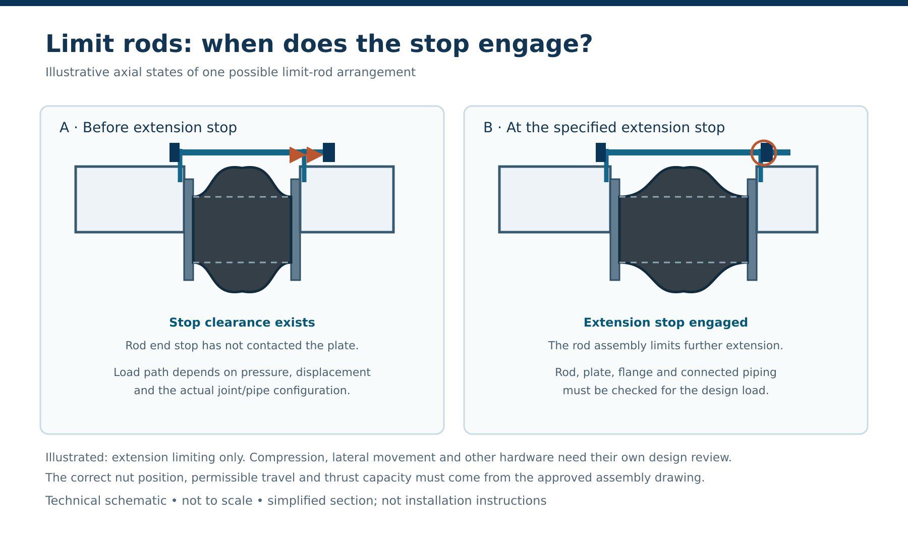
Caption: A possible extension-stop arrangement before and after stop contact. The illustrated clearance is conceptual, not a prescribed setting or installation instruction.
Consider a rod with an outer stop nut set at a specified clearance from its plate in the installed condition. Before contact, that stop does not provide the same direct axial restraint as a rod whose load-bearing hardware is already engaged. The joint may extend until the clearance is taken up, subject to the movement capability and all other system constraints. At contact, the rod, stop, plate and attached flanges become part of the extension load path. That transition changes the stiffness and forces in the system; the stop must be designed for the applicable pressure and movement case.
Compression is a separate question. An outer extension stop need not prevent the joint from shortening. Internal nuts, compression sleeves or other details may restrict compression in a specified design, but their presence, settings and load capacity cannot be inferred from an exterior photograph. A rod assembly intended to transfer thrust from the start may instead require its load-bearing nuts positioned against the plates at the installed length. These configurations should not share an assumed clearance setting.
The important review is state by state: the installed cold position; normal hot or running position; start, stop and transient conditions; and the hydrostatic test arrangement. Record which contacts are open and which are engaged in each state. Where lateral movement is required, also check whether plate geometry and hardware allow that offset without binding or transferring an unanticipated bending load. Manufacturer guidance distinguishes these rod arrangements and calls for the settings to be established for the actual system. procoproducts.com
Check movement and pressure as one operating envelope
An extension allowance is not the same as usable axial travel in service. Installed length, any cold preset, thermal displacement and pressure-induced extension all affect how much travel remains before a stop engages. If the installation starts with a lateral offset, the joint also has less capacity available for additional lateral movement. Use the manufacturer’s combined-movement limits for the selected size and construction.
For each relevant operating case, the review should state the intended axial extension or compression, lateral displacement and angular rotation at the joint. Then identify the force path and stop-contact state at that position. A test pressure higher than normal operating pressure may govern thrust and rod hardware even if the test occurs with little thermal movement. Conversely, the hot operating position may govern available clearance. The allowable pressure, temperature and movement of the rubber body must be confirmed separately from the capacity of the restraint hardware.
Neither the rubber body nor a pair of rods should be used to correct a poorly aligned pipeline. Mating flange geometry, installation length and pipe support affect the actual starting position. The approved assembly drawing and the manufacturer’s installation instructions take priority over a generic sketch.
What changes at a pump connection?
Near a pump, the force calculation must be completed at the pump nozzle, not stopped at the joint. A tie-rod arrangement may establish a thrust path between its end flanges, yet other pipe forces and moments can still reach the pump: weight from unsupported piping, thermal growth, misalignment, guide friction and reactions from the joint’s deflection. A flexible component cannot certify that the nozzle loads are acceptable.
The pump supplier should provide allowable nozzle forces and moments, and the piping engineer should evaluate the installed piping against those values for the specified load cases. State whether the joint is on suction or discharge and supply the pressure at that specific location. On suction, assess the minimum pressure and any vacuum condition separately; a positive-pressure thrust calculation does not prove vacuum suitability. On discharge, include the pressure cases relevant to starting, stopping, shutoff, surge and testing.
Information needed to review an anchored or tied proposal
The following review sheet makes the selection reproducible. Leave an unknown item marked to be confirmed rather than filling it with a typical catalogue value.
| Item | Information to record or confirm |
|---|---|
| Joint and connection | Selected construction and size; flange drilling, faces, thickness and installed face-to-face length. |
| Pressure cases | Minimum, normal, maximum, transient and test pressures at the joint; gauge or absolute basis; external pressure where relevant. |
| Effective area | Manufacturer-confirmed value or thrust factor for the proposed construction and size. |
| Temperature and medium | Operating and test temperatures; fluid and compatibility requirements. |
| Movement | Axial extension/compression, lateral and angular movement, cold preset and simultaneous combinations. |
| Restraint boundary | Locations and design responsibilities of anchors, guides, supports, bends, equipment and joint. |
| Rod detail | Intended function; number and size; plate, nut and flange details; initial settings; contact states and verified load capacity. |
| Equipment acceptance | Allowable nozzle forces and moments and the resulting calculated loads in each relevant case. |
For a proposed Mingchao joint, product dimensions, pressure/vacuum capability, effective area, combined movement and restraint capacity must be confirmed for the actual configuration. The product page and datasheet identify a configuration for discussion; they do not replace a project-specific restraint drawing or a piping stress review. Mingchao
Conclusion
Pressure thrust is straightforward to estimate once the correct pressure case and effective area are known. The engineering decision is where that thrust is reacted throughout the joint’s travel. An anchor-defined system and a rod-restrained assembly can both be valid, but they require different verified load paths. If a stop engages only after a clearance closes, the system has two distinct mechanical states; check both before approving axial movement or pump nozzle loads.
Technical References and Related Products
Mingchao product and project information
- Restrained Rubber Expansion Joint with Tie Rods — product configuration and enquiry context.
- Restrained Rubber Expansion Joint with Tie Rods — Technical Datasheet (PDF) — product-specific downloadable document; confirm project values before specification.
- Technical Information & Project Requirements — information to prepare for a technical review.
Related Mingchao article
- Rubber Expansion Joints for Pump Suction and Discharge: Selection Requirements — pressure cases, vacuum suitability and pump connection review.