
On this page
- Suction and Discharge Connections Need Separate Operating Data
- Suction-Side Selection: Confirm Vacuum Capability
- Discharge-Side Selection: Identify the Pressure Cases
- Pressure Thrust: Calculate the Force, Then Determine Its Load Path
- Tie Rods, Supports and Anchors Have Different Functions
- Specify Movement and Installation Geometry Together
- Confirm Materials and Mating Flanges
- Pump Connection Review Sheet
- Technical References and Related Products
A rubber expansion joint at a pump connection must do more than fit between two flanges. It must withstand the pressure and temperature at that location, accommodate the required movement, and work with the piping restraint arrangement without imposing unacceptable loads on the pump.
Matching nominal diameter, flange drilling and face-to-face length is therefore only part of the selection. The suction and discharge connections need separate checks, even when the joints look identical.
This article addresses rubber expansion joints in centrifugal-pump piping. Final selection should follow the pump manufacturer’s instructions, the joint manufacturer’s confirmed capabilities and the approved piping design.
Suction and Discharge Connections Need Separate Operating Data
“Suction” does not necessarily mean vacuum. A pump supplied from a pressurized vessel or a flooded system may have positive pressure at its inlet. Other installations may experience sub-atmospheric pressure during operation or particular operating events.
Similarly, normal discharge pressure is not the only pressure relevant to the discharge joint.
| Selection item | Suction connection | Discharge connection |
|---|---|---|
| Pressure range | Minimum and maximum pressure at the joint, including any vacuum condition | Operating range and applicable shutoff, transient and test conditions |
| Joint construction | Confirm vacuum suitability where required, as well as positive-pressure capability | Confirm pressure capability at the specified temperature |
| Piping arrangement | Review inlet geometry and the pump manufacturer’s suction-piping requirements | Review the surrounding valves, supports and restraint arrangement |
| Mechanical loading | Check joint reactions, piping loads and permitted pump nozzle loads | Check pressure thrust, joint reactions and permitted pump nozzle loads |
| Movement | Define actual axial, lateral and angular movement | Define actual axial, lateral and angular movement |
Record whether each pressure is gauge or absolute. A value without a pressure reference can lead to a different interpretation of the required operating condition.
Suction-Side Selection: Confirm Vacuum Capability
A positive-pressure rating does not establish a rubber expansion joint’s vacuum capability. Obtain confirmation for the selected construction, diameter, temperature and installed condition.
The supplier needs the lowest expected pressure at the joint—not simply a statement that the joint is “for pump suction.” Where relevant, describe priming, draining and other operating events that may change the pressure.
Some constructions use reinforcement or a vacuum support ring. Whether that is necessary, and whether a particular arrangement is suitable, must be confirmed for the selected joint. An internal ring should not be added on site as an improvised correction.
Proco’s installation guidance for its Series 230 products also cautions against installing those joints in an extended condition for vacuum service. The broader selection point is to check vacuum capability together with the intended installed length and movement, rather than treating it as an independent catalogue number.
Keep the hydraulic review separate from the joint’s mechanical rating. A vacuum-capable joint does not, by itself, establish that the suction-piping arrangement is acceptable. The pump supplier should confirm the inlet arrangement and the required suction conditions.
Discharge-Side Selection: Identify the Pressure Cases
For a centrifugal pump, a quoted duty-point pressure describes one operating condition. The joint specification should identify the other pressure cases applicable to the installation.
Ask the system designer to confirm:
- Normal and maximum operating pressure at the joint.
- Any relevant shutoff condition.
- Pressure transients associated with starting, stopping or valve operation.
- Hydrostatic test pressure and test temperature.
A flange designation alone does not establish the pressure rating of the assembled rubber joint. The rubber body, reinforcement, flange arrangement and other components must be suitable together.
Pressure fluctuations also need their own assessment. KSB distinguishes the movement-isolation function of an expansion joint from the treatment of pressure surges. A rubber joint should not be specified as the system’s water-hammer protection device.
Pressure Thrust: Calculate the Force, Then Determine Its Load Path
Internal pressure creates an axial separating tendency in an unrestrained expansion joint. A basic pressure-thrust calculation is:
F = Δp × Aₑ
Where:
- F is pressure thrust.
- Δp is internal pressure minus external pressure at the joint.
- Aₑ is the joint’s effective pressure area, supplied by the manufacturer.
Here, Δp is not the difference between pump discharge pressure and pump suction pressure.
The effective area is related to the joint construction. Do not substitute the pipe bore area or calculate an area from the nominal diameter unless the manufacturer confirms that basis. Manufacturer literature may provide an effective area or a thrust factor for the selected construction.
For illustration, assume:
| Input | Assumed value |
|---|---|
| Internal minus external pressure | 1.0 MPa |
| Effective area | 20,000 mm² |
| Pressure thrust | 1.0 N/mm² × 20,000 mm² = 20 kN |
These are calculation assumptions, not ratings for a Mingchao product.
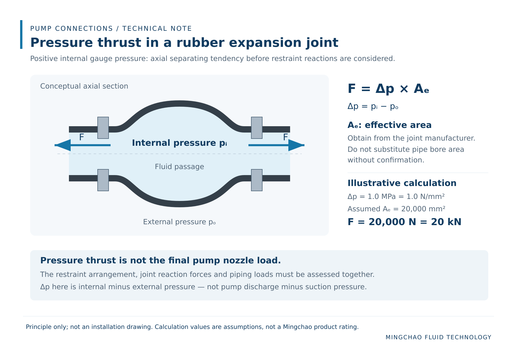
The result is a pressure-thrust component, not a final pump nozzle load. The next question is where that force is carried. The answer depends on the joint restraint, piping anchors and the complete installation. Joint movement reactions and other piping forces must also be included in the mechanical assessment.
Tie Rods, Supports and Anchors Have Different Functions
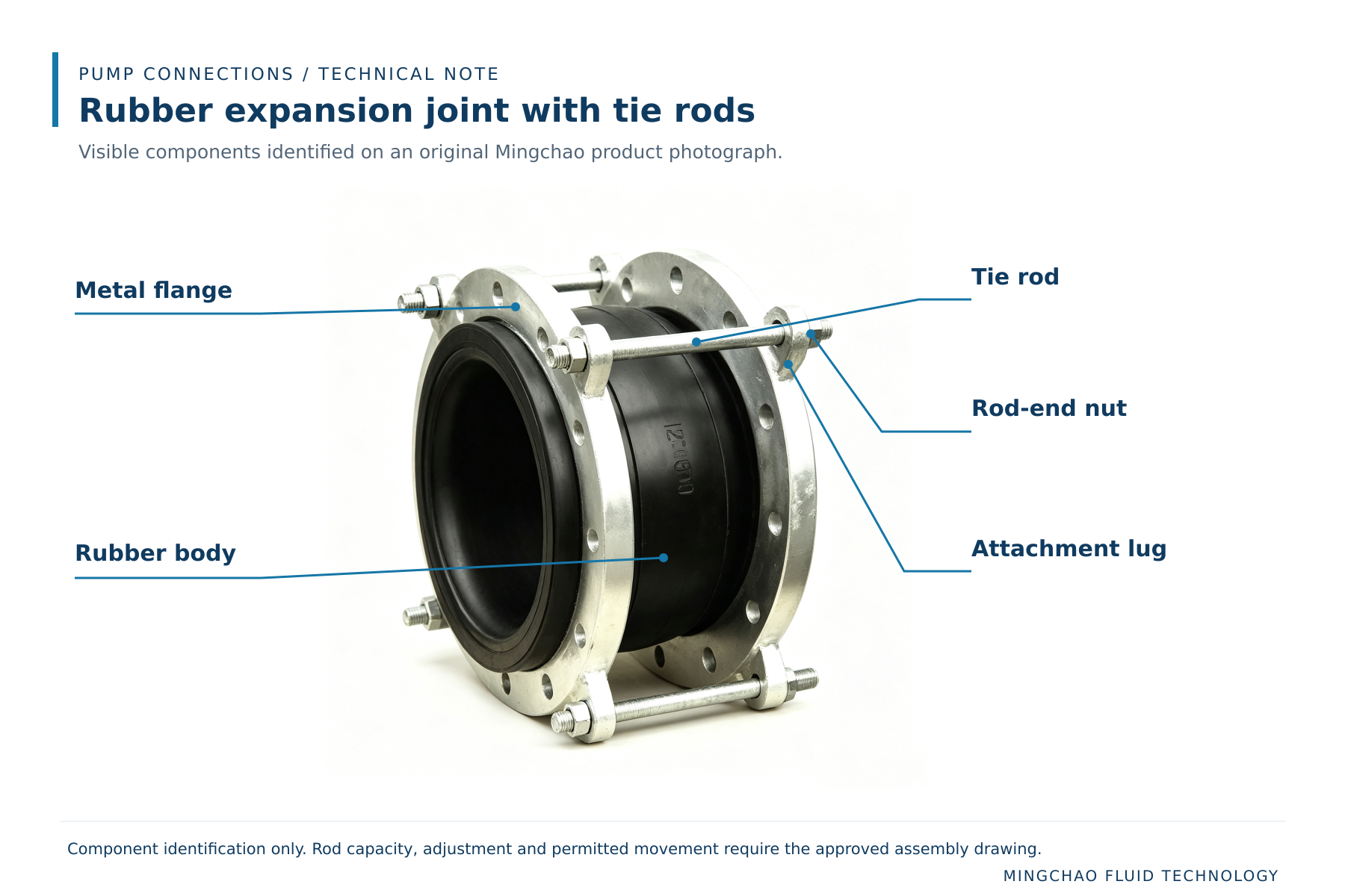
A photograph showing rods around a joint is not enough to establish the assembly’s permitted movement or load capacity.
For the proposed assembly, obtain a drawing that identifies:
- The purpose and capacity of the rod arrangement.
- Its specified settings or clearances.
- The movements it permits and restricts.
- Any provisions against excessive extension or compression.
- The loads that must be carried by the surrounding piping structure.
Terminology such as “tie rods,” “control units” and “limit rods” should be read with the manufacturer’s drawing. The names alone do not fully describe how an assembly behaves.
Garlock’s guidance describes control units as protection against excessive movement and explicitly states that they are not a replacement for adequate pipeline anchoring.
Pipe supports must carry the intended weight of the pipe, contained fluid and associated equipment. The flexible joint should not be used to suspend an unsupported valve or pipe section.
For the pump, the acceptance check is the resulting force and moment at each nozzle against the pump manufacturer’s allowable values. A flexible connection can still transmit load. KSB’s piping guidance specifically addresses the risk of pressure forces at expansion joints exceeding permissible pump flange loads.
Specify Movement and Installation Geometry Together
Describe the movement at the joint location. “Vibration service” or “thermal expansion” is not a complete movement specification.
Separate the required axial extension, axial compression, lateral displacement and angular movement. State which movements occur together and whether an installation offset is already present.
Do not assume the individual maximum movements in a catalogue can all occur simultaneously. For example, Proco identifies movement values in its Series 230 tables as non-concurrent. Use the selected manufacturer’s combined-movement limits.
The installation drawing should also identify the required cold face-to-face length and flange alignment. Any intentional preset must be approved and documented. Pulling a joint into a gap to make the bolts fit can consume movement capacity before the pump operates.
Single-sphere and double-sphere joints should be compared against these requirements. Additional spheres do not automatically make a joint more suitable for a pump connection.
Confirm Materials and Mating Flanges
Specify the actual fluid, concentration where relevant, temperature range and any cleaning or flushing media. The material review should address the complete joint construction, including wetted surfaces and external exposure.
For the mating flanges, provide more than the nominal pressure class. Confirm the drilling, sealing-face geometry and available contact surface against the joint manufacturer’s requirements.
Installation details—including bolting, tightening procedure and whether additional gaskets are appropriate—should come from the approved instructions for that joint. Avoid transferring a procedure from a different flange or joint construction.
Pump Connection Review Sheet
The following information gives the joint supplier and pump supplier a common basis for review.
| Information required | What to provide |
|---|---|
| Pump and connection | Pump manufacturer, model, nozzle size, suction or discharge location |
| Fluid | Medium, concentration and relevant solids or contaminants |
| Temperature | Normal, minimum and maximum; cleaning conditions where applicable |
| Pressure | Minimum and maximum at the joint; identify gauge or absolute values |
| Other pressure cases | Applicable shutoff, transient and hydrostatic-test conditions |
| Dimensions | Nominal size, flange details and required installed face-to-face length |
| Movement | Axial, lateral and angular requirements; concurrent movements and cycles |
| Restraint arrangement | Drawing showing rods, anchors, guides and supports |
| Pump limits | Allowable nozzle forces and moments from the pump supplier |
| Joint data | Confirmed pressure/vacuum limits, effective area and relevant reaction data |
| Installation review | Approved assembly drawing and installation instructions |
Mark missing information as to be confirmed. Do not replace unknown values with assumptions in a purchase specification.
Mingchao Fluid Technology can review the supplied operating conditions, connection dimensions and movement requirements to propose a rubber expansion joint configuration. Confirmation of the overall piping arrangement and allowable pump nozzle loads remains part of the project’s engineering review.
Technical References and Related Products
Mingchao product and project information
- Restrained Rubber Expansion Joint with Tie Rods — Technical Datasheet (PDF)
- KXT Single Sphere Rubber Expansion Joint
- Technical Information & Project Requirements
Related articles
- Technical Requirements for Rubber Expansion Joint Replacement: Seven Key Checks
- Single-Sphere and Double-Sphere Rubber Expansion Joints: Selection Considerations
External technical references
- KSB Centrifugal Pump Lexicon — Expansion Joint
- KSB Centrifugal Pump Lexicon — Piping
- Garlock Expansion Joints — Technical Manual (PDF)
- Proco Series 230 — Product and Technical Data (PDF)
External references explain engineering principles and their manufacturers’ products. Their numerical ratings must not be applied to a Mingchao assembly.