
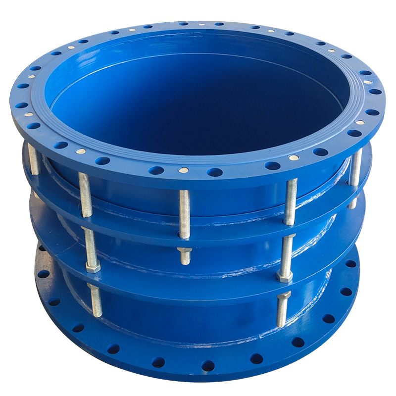
Dismantling & Telescopic Joints
VSSJA-2 (B2F) Double Flange Restrained Telescopic Joint
The VSSJA-2 (B2F) double flange restrained telescopic joint is designed to provide axial compensation and installation adjustment in flanged piping systems while using limit studs to control excessive extension and help protect connected pipelines, valves and equipment.
Also searched as a double flange telescopic joint, restrained telescopic joint, double flange restrained expansion joint or double flange limited telescopic joint.
- Standard Sizes
- DN65–DN1600
- Large / Custom Sizes
- Up to DN3600 on request
- Compensation Length
- 50 / 65 / 130 / 150 mm, depending on size
- Pressure Options
- 0.6 / 1.0 MPa
- Function
- Axial Compensation + Limited Expansion Control
- Structure
- Double Flange + Follower + Limit Studs
- Body / Follower
- QT450-10 / Q235A
- Gasket
- NBR / EPDM / CR
CustomizationFlange drilling, dimensions and large-size configurations can be reviewed according to confirmed project requirements and approved drawings.
Project Configuration
Mingchao can customize the product configuration based on the technical information, operating conditions and dimensional data you provide. Final configuration can be reviewed and manufactured to the approved project drawing.
VSSJA-2 (B2F) Double Flange Restrained Telescopic Joint Overview
The VSSJA-2 (B2F) double flange restrained telescopic joint provides controlled axial adjustment between two flanged pipeline connections. Its telescopic structure allows the connected piping to accommodate installation tolerance and axial movement within the confirmed compensation range.
Limit studs and nuts are used to control maximum extension, helping prevent excessive telescopic movement from causing pull-out, leakage or damage to connected pipeline equipment.
The double-flange configuration makes B2F suitable for water-supply and drainage systems, wastewater treatment, industrial pipelines, pump and valve connections, municipal engineering and other flanged piping installations requiring axial compensation with mechanical movement limitation.
Axial Compensation & Restrained Movement
B2F is designed to permit axial compensation within the selected product range while mechanically limiting excessive extension. During normal adjustment, the telescopic section provides longitudinal movement. When the maximum permitted extension is reached, the limit-stud arrangement restricts further separation.
The required compensation length depends on nominal size and the selected product configuration. Mingchao catalog lists published compensation lengths of 50 mm, 65 mm, 130 mm and 150 mm depending on size.
Dimensions, Pressure Options & Flange Configuration
The published B2F catalog table covers DN65 to DN3600. The main table below presents the verified product geometry from DN65 to DN1600; flange drilling must be confirmed against the required project standard and approved drawing.
| Nominal Diameter | External Diameter Dw (mm) | Overall Length L (mm) | Length L1 (mm) | Compensation ΔL (mm) |
|---|---|---|---|---|
| DN65 | 76 | 340 | 105 | 50 |
| DN80 | 89 | 340 | 105 | 50 |
| DN100 | 108 | 340 | 105 | 50 |
| DN100 | 114 | 340 | 105 | 50 |
| DN125 | 133 | 340 | 105 | 50 |
| DN125 | 140 | 340 | 105 | 50 |
| DN150 | 159 | 340 | 105 | 50 |
| DN150 | 168 | 340 | 105 | 50 |
| DN200 | 219 | 340 | 105 | 50 |
| DN250 | 273 | 340 | 105 | 50 |
| DN300 | 325 | 370 | 130 | 65 |
| DN350 | 377 | 370 | 130 | 65 |
| DN400 | 426 | 370 | 130 | 65 |
| DN450 | 480 | 370 | 130 | 65 |
| DN500 | 530 | 370 | 130 | 65 |
| DN600 | 630 | 370 | 130 | 65 |
| DN700 | 720 | 370 | 130 | 65 |
| DN800 | 820 | 600 | 220 | 130 |
| DN900 | 920 | 600 | 220 | 130 |
| DN1000 | 1020 | 600 | 220 | 130 |
| DN1200 | 1220 | 640 | 220 | 130 |
| DN1400 | 1420 | 640 | 220 | 130 |
| DN1500 | 1520 | 640 | 220 | 130 |
| DN1600 | 1620 | 640 | 220 | 130 |
Larger Sizes Available: Sizes above DN1600 can be manufactured up to DN3600 on request. Dimensions, flange drilling and other project-specific requirements are confirmed according to the required size and approved drawings.
Materials, Gasket & Limit-Stud Construction
The telescopic body and follower provide the adjustable mechanical structure, while the elastomer gasket forms the seal around the sliding section. Limit studs and nuts control the maximum permitted extension of the joint.
| Component | Published Material |
|---|---|
| Body | QT450-10 or Q235A |
| Follower | QT450-10 or Q235A |
| Gasket | NBR / EPDM / CR |
| Limited Short Pipe | Q235A |
| Nut | Q235A / 20# |
| Long Stud | Q235A / 35# |
| Short Stud | Q235A / 35# |
Applications for Waterworks, Valves, Pumps & Municipal Piping
Water Supply Systems
Axial adjustment and controlled movement for flanged water-distribution pipelines.
Drainage & Sewage Systems
Telescopic connection for drainage and sewage pipelines where installation tolerance or axial movement must be accommodated.
Wastewater Treatment Plants
Used around process piping, valves and equipment in wastewater-treatment systems.
Pump & Valve Connections
Provides installation adjustment and controlled axial compensation around flanged pumps and valves.
Municipal & Industrial Pipelines
Suitable for municipal and industrial pipelines requiring double-flange telescopic adjustment.
Fire Protection Piping
Used in flanged fire-protection pipeline systems according to confirmed project pressure, flange and installation requirements.
How to Select a B2F Double Flange Telescopic Joint
Correct selection depends on the required axial adjustment, pressure, connection dimensions and restraint condition. Provide the project information below so the B2F configuration can be confirmed.
- Nominal diameter / DN
- Required axial compensation / adjustment
- Installation length
- Working / design pressure
- Medium
- Operating temperature
- Body material requirement
- Gasket material
- Flange standard / drilling
- Required restraint / maximum extension condition
- Connected equipment: valve / pump / pipeline
- Quantity
- Project drawing / mating-flange dimensions
Large-size requirement if above DN1600
B2F Telescopic Joint vs. C2F Dismantling Joint
| Product Type | Configuration |
|---|---|
| VSSJA-2 (B2F) | Primary function: axial compensation and limited / restrained movement. Telescopic movement is permitted within the confirmed range, while limit studs restrict excessive extension. Primary search intent: double flange telescopic joint. Typical selection: pipeline systems requiring axial compensation plus mechanical movement limitation. |
| VSSJAF (C2F) | Primary function: installation adjustment, dismantling and force transmission. Selected primarily for equipment installation or removal and force-transmission duty. Primary search intent: double flange dismantling joint. Typical selection: valves, pumps and equipment requiring installation, disassembly and force-transmission capability. |
Installation, Adjustment & Limit-Stud Setup
Use the approved product configuration and piping-system design for final installation.
Confirm Selection
Confirm DN, installation length, compensation requirement, pressure and flange configuration before installation.
Align Flanges
Align both mating flanges before final tightening.
Set Position
Adjust the telescopic section to the required installation position within the confirmed allowable range.
Establish Seal
Tighten the follower or gland fasteners gradually and evenly to establish reliable gasket sealing.
Set Limit Studs
Set and secure the limit studs according to the approved installation position and allowable compensation requirement.
Avoid Misalignment
Do not use the joint to correct excessive pipeline misalignment.
Support Piping
Support connected piping and equipment so that unintended pipe weight is not transferred to the joint.
System Restraint
Confirm anchors, supports and system restraint according to the piping design.
Final Inspection
Recheck limit nuts, flange fasteners and sealing condition after installation.
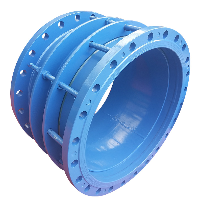
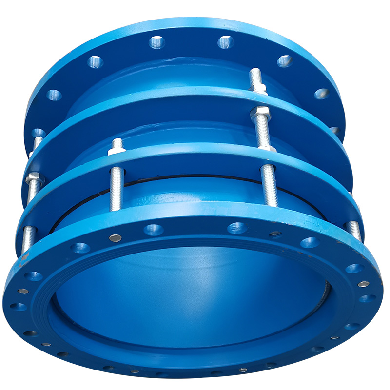
Real B2F Product & Technical Photos
Technical Documents / Reference Information
- B2F Product Technical Data
- B2F Dimension Table
- B2F Technical Drawing
- Project-specific flange drawing available after configuration review
Technical Datasheet
VSSJA-2 (B2F) Double Flange Restrained Telescopic Joint
Technical Datasheet · PDF