Rubber Expansion Joints
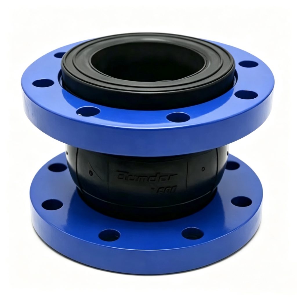
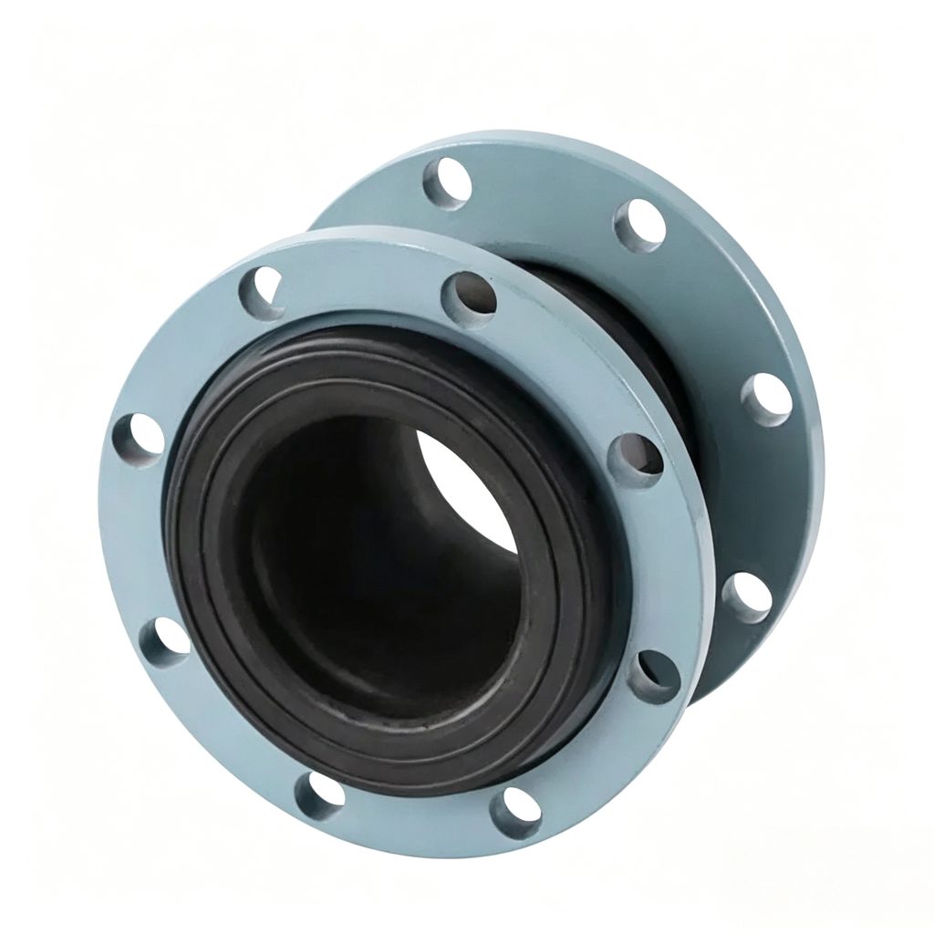
KDF High-Pressure Single Sphere Rubber Expansion Joint
The KDF High-Pressure Single Sphere Rubber Expansion Joint is designed for piping systems where pressure capability, vibration isolation and controlled movement must be considered together. Mingchao can manufacture the joint to project-specific pressure class, face-to-face length, flange drilling, elastomer, reinforcement and dimensional requirements based on the approved drawing and operating conditions.
HIGH-PRESSURE RUBBER CONNECTION · DRAWING-BASED CUSTOM ENGINEERING
- Configuration
- Single Sphere
- Selection Basis
- Pressure · Temperature · Medium · Movement
- Custom Engineering
- Flange · Length · Dimensions · Materials
Project Configuration
Mingchao can customize the product configuration based on the technical information, operating conditions and dimensional data you provide. Final configuration can be reviewed and manufactured to the approved project drawing.
KDF High-Pressure Single Sphere Rubber Expansion Joint — Product Overview
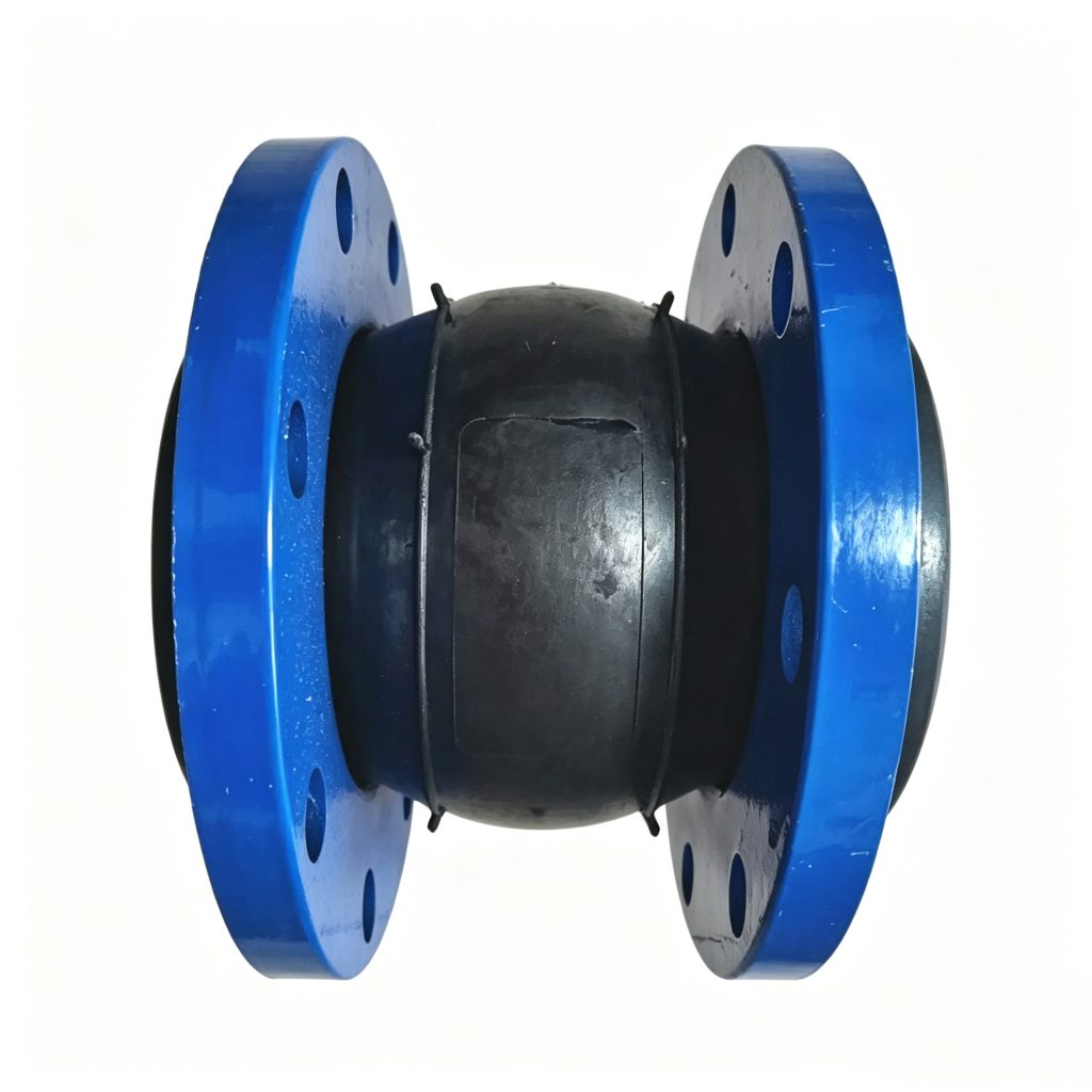
The KDF High-Pressure Single Sphere Rubber Expansion Joint is a pressure-oriented flexible piping connection for applications where vibration isolation, controlled movement and operating pressure must be evaluated together. Compared with a general-purpose single-sphere joint, the KDF selection process places greater emphasis on the complete pressure condition, reinforcement configuration, flange connection and piping restraint arrangement.
What “High Pressure” Means for a Rubber Expansion Joint
A high-pressure rubber expansion joint cannot be selected from the flange rating alone. The allowable working condition depends on nominal size, operating temperature, elastomer, reinforcement construction, face-to-face length, movement demand and the actual pressure profile of the piping system. Pressure peaks, surge conditions and vacuum requirements should therefore be declared before the joint is selected.
There is no one universal maximum pressure for all KDF sizes, temperatures and configurations. The allowable condition is confirmed for the specific project.
Reinforced Single-Sphere Construction
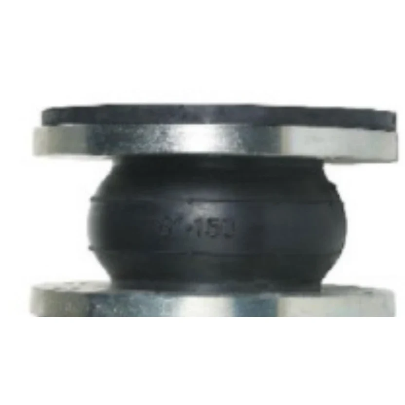
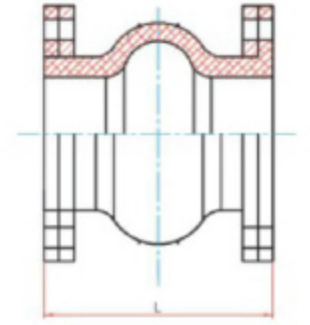
The KDF configuration combines a single-sphere elastomeric body with internal reinforcement and flanged pipe connections. For high-pressure service, the rubber body, reinforcement system, flange configuration and restraint requirements are reviewed as one assembly rather than as independent components.
The exact reinforcement construction and layer arrangement require factory confirmation for the approved KDF configuration; no universal cord or wire-layer count is published.
Pressure, Temperature & Size Must Be Selected Together
Published flange pressure classes do not automatically define the allowable working pressure of the rubber element. Higher temperature can reduce pressure capability, and larger diameters or demanding movement conditions may require different engineering limits. Mingchao therefore confirms the working condition against the complete operating requirement before final drawing approval.
Selection must consider DN, working and peak pressure, temperature, medium, elastomer, reinforcement, movement, face-to-face length, flange configuration and restraint or anchoring condition together.
KDF Dimensions & Technical Data
The following 32 published rows provide KDF high-pressure single-sphere dimensions and movement data for preliminary selection.
| DN | inch | L_mm | Axial_Extension_mm | Axial_Compression_mm | Lateral_Displacement_mm | Deflection_Angle_deg |
|---|---|---|---|---|---|---|
| 50 | 2 | 105 | 7 | 10 | 10 | 15 |
| 65 | 2.5 | 115 | 7 | 13 | 11 | 15 |
| 80 | 3 | 135 | 8 | 15 | 12 | 15 |
| 100 | 4 | 150 | 10 | 19 | 13 | 15 |
| 125 | 5 | 165 | 12 | 19 | 13 | 15 |
| 150 | 6 | 185 | 12 | 20 | 14 | 15 |
| 200 | 8 | 210 | 16 | 25 | 22 | 15 |
| 250 | 10 | 230 | 16 | 25 | 22 | 15 |
| 300 | 12 | 245 | 16 | 25 | 22 | 15 |
| 350 | 14 | 255 | 16 | 25 | 22 | 15 |
| 400 | 16 | 255 | 16 | 25 | 22 | 15 |
| 450 | 18 | 255 | 16 | 25 | 22 | 15 |
| 500 | 20 | 255/290 | 16 | 25 | 22 | 15 |
| 600 | 24 | 260 | 16 | 25 | 22 | 15 |
| 700 | 28 | 260/300 | 16 | 25 | 22 | 15 |
| 750 | 30 | 260/300 | 16 | 25 | 22 | 15 |
| 800 | 32 | 260/300 | 16 | 25 | 22 | 15 |
| 900 | 36 | 260/300 | 16 | 25 | 22 | 15 |
| 1000 | 40 | 260/300/350 | 18 | 26 | 22 | 15 |
| 1100 | 44 | 300 | 18 | 26 | 22 | 15 |
| 1200 | 48 | 260/300 | 18 | 26 | 24 | 15 |
| 1300 | 51 | 300/400 | 18 | 26 | 24 | 15 |
| 1400 | 56 | 350/400 | 20 | 28 | 26 | 15 |
| 1500 | 60 | 350 | 20 | 35 | 26 | 15 |
| 1600 | 64 | 350 | 25 | 35 | 30 | 10 |
| 1800 | 72 | 400/450 | 25 | 35 | 30 | 10 |
| 2000 | 80 | 360/450 | 25 | 35 | 30 | 10 |
| 2200 | 88 | 420/450/500 | 25 | 35 | 30 | 10 |
| 2400 | 96 | 360/400/500 | 25 | 35 | 30 | 10 |
| 2600 | 104 | 450/500 | 25 | 35 | 30 | 10 |
| 2800 | 112 | 580 | 25 | 35 | 30 | 10 |
| 3000 | 120 | 500/550 | 25 | 35 | 30 | 10 |
Values are published catalog references. Final pressure, movement and dimensional suitability must be confirmed against the complete operating conditions and approved drawing.
Extended High-Pressure Engineering Specification Matrix
| Engineering_Field | Published_Status |
|---|---|
| Nominal Size — DN / NPS | KDF catalog table / approved drawing |
| Face-to-Face Length | KDF catalog table or custom approved drawing |
| Flange Standard | Project-specific / catalog reference available |
| Flange Pressure Class | Project-specific engineering review |
| Flange Outside Diameter | According to approved drawing |
| PCD / Bolt Circle | According to approved drawing |
| Bolt Quantity | According to approved drawing |
| Bolt Hole Diameter / Thread | According to approved drawing |
| Flange Thickness | According to approved drawing |
| Working Pressure | Factory confirmation required by size and condition |
| Pressure Peaks / Surge | Declare for engineering review |
| Hydrostatic / Test Pressure | Project-specific inspection requirement |
| Burst Pressure | Factory confirmation required |
| Vacuum Requirement | Declare for engineering review |
| Operating Temperature | Project-specific |
| Pressure-Temperature Selection | Engineering review required |
| Axial Compression | KDF catalog table / project-specific |
| Axial Extension | KDF catalog table / project-specific |
| Lateral Movement | KDF catalog table / project-specific |
| Angular Deflection | KDF catalog table / project-specific |
| Combined Movement | Engineering review required |
| Effective Area / Thrust Factor | Calculated during engineering review |
| Spring Rate | Factory confirmation required |
| Weight | Factory confirmation required |
| Inner Elastomer | Selected for medium and condition |
| Outer Elastomer | Selected for environment and condition |
| Reinforcement Construction | Factory confirmation required |
| Flange Material | Available to project specification |
| Flange Coating / Surface Treatment | Available to project specification |
| Optional Control / Tie Rods | Project-specific engineering review |
| Customer Drawing / CAD | Required for non-standard configuration |
| Inspection / Testing Requirements | According to project specification |
Fields without a Mingchao source-confirmed numeric value remain project-specific, drawing-based or factory-confirmation items.
Flange Standards, Pressure Classes & Custom Drilling
Flange pressure class and rubber-joint working pressure are different engineering parameters. PN or ASME Class designations define the specified flange system, while the allowable pressure of the complete rubber expansion joint depends on the body construction, size, temperature, medium, movement and reinforcement configuration.
PN25 or ASME Class 300 flange configurations can be reviewed where required by the project. The flange designation must not be interpreted as the rubber element’s allowable working pressure without engineering confirmation of the complete joint configuration.
Flange pressure class does not by itself define the allowable working pressure of the rubber element or complete expansion joint. Custom flange standard, outside diameter, PCD, drilling, bolt pattern and thickness can be reviewed against the approved drawing.
Axial, Lateral & Angular Movement
The Mingchao KDF catalog publishes axial extension, axial compression, lateral displacement and deflection-angle references by nominal size. These values are reproduced in the catalog table rather than borrowed from a generic KXT product.
Movement directions are not automatically additive. Combined movement, pressure, temperature, size and installation geometry must be reviewed together, and the installed piping must remain correctly aligned and supported.
Rubber Materials & Media Compatibility
| Elastomer | Typical Service Consideration | Important Selection Note |
|---|---|---|
| EPDM | Water, hot water, wastewater, HVAC and outdoor service | Oil or fuel compatibility and temperature must be confirmed |
| NBR | Oil, diesel, lubricating oil and oily service | Temperature, ozone and exact medium must be confirmed |
| NR | General water, vibration and mild abrasive conditions | Not universal for oil, high temperature or aggressive chemicals |
| CR / Neoprene | Seawater, outdoor and general industrial service | Chemical compatibility remains project-specific |
| FKM | Demanding oil, chemical or higher-temperature conditions | Exact medium, concentration, temperature and pressure must be confirmed |
Material compatibility must be confirmed against the actual medium, concentration, operating temperature and pressure.
The catalog includes NR, EPDM, CR, IIR, NBR and VITON-type material categories; this page does not claim drinking-water, WRAS, NSF, ACS or other approvals.
Custom Pressure, Dimensions & Drawing-Based Fabrication
Mingchao supports drawing-based custom fabrication for pressure class, face-to-face length, flange drilling, bolt pattern, dimensions, materials, coatings, elastomers and connection details. Custom requirements are reviewed for manufacturability and the specified pressure, temperature, medium and movement conditions before production.
Custom dimensional and geometric configurations can be manufactured according to approved customer or project drawings, subject to engineering and manufacturability review. Custom geometry remains subject to engineered pressure, temperature and movement limits.
Pressure Thrust, Anchors & Optional Control Rods
Internal pressure produces pressure thrust at a rubber expansion joint. The joint does not replace the piping anchors, guides and supports required to control that load and the connected pipeline.
Optional control or tie rods can be reviewed when the project restraint concept requires them. Their arrangement must follow the piping design, movement envelope and approved drawing; no universal anchor spacing, guide distance or thrust value is inferred here.
High-Pressure Applications & Selection Boundaries
Typical engineering contexts include pump and equipment connections, pressurized water systems, industrial utility piping, HVAC and chilled-water systems where pressure requirements justify the configuration, process piping, and replacement projects requiring non-standard flange or face-to-face geometry.
Actual suitability depends on pressure, temperature, medium, movement, reinforcement, flange connection and piping design. These applications are not blanket approvals.
KDF High-Pressure vs. KXT Standard Single Sphere
The KXT Single Sphere Rubber Expansion Joint owns the general single-sphere rubber expansion-joint intent.
KDF is the pressure-oriented single-sphere selection, with greater emphasis on the declared pressure profile, reinforcement configuration, pressure-temperature-medium relationship, flange requirements and restraint review.
No unsupported MPa increase, percentage improvement or service-life comparison is claimed.
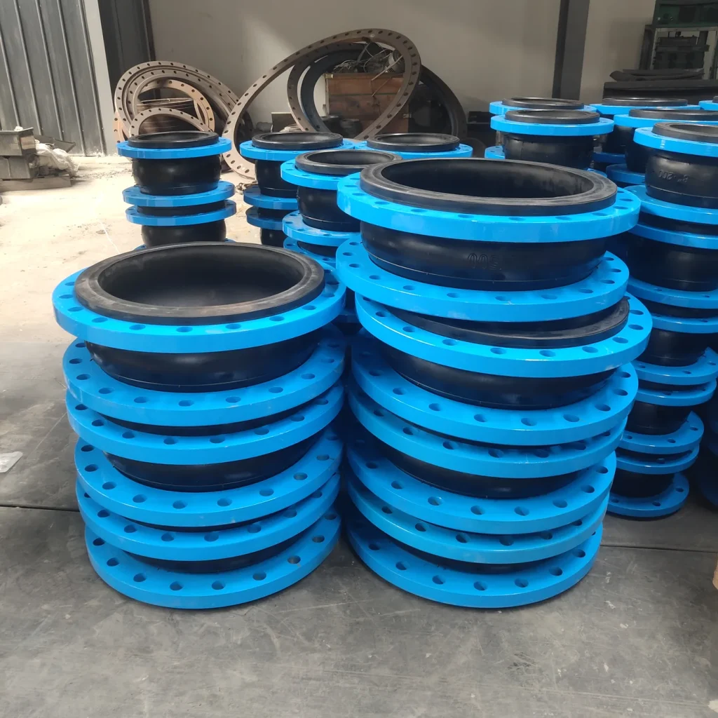
KDF high-pressure single-sphere configuration Single Sphere vs. High-Pressure Double Sphere
KDF high-pressure single-sphere configuration uses a high-pressure single-sphere configuration. A high-pressure double-sphere configuration uses two spherical convolutions and is a separate product selection.
The structural difference does not establish a universal pressure or movement advantage. Required pressure, size, movement, face-to-face length and piping geometry must be reviewed for the selected configuration.
Inspection, Testing, Drawings & Project RFQ
Send Pressure Requirements & Drawing for Engineering Review.
For accurate quotation, provide the complete operating pressure profile, temperature, medium, DN, flange system, face-to-face length, movement, restraint concept, inspection requirements and drawing. If catalog dimensions do not match the installation, Mingchao can review a custom configuration from the approved drawing.
Current Chinese reference standards for flexible rubber joints include GB/T 26121-2010 and HG/T 2289-2017. Applicable manufacturing, testing and documentation requirements are confirmed according to the project specification and order. These references are not presented as product certification.
- DN / NPS
- Required flange standard
- Required flange pressure class
- Working pressure
- Maximum / peak / surge pressure
- Operating temperature
- Medium / fluid
- Concentration if chemical
- Vacuum requirement if any
- Face-to-face length
- Axial compression requirement
- Axial extension requirement
- Lateral movement requirement
- Angular movement requirement
- Combined movement condition
- Flange OD if replacement
- PCD / bolt circle if replacement
- Bolt quantity
- Bolt-hole diameter / thread
- Flange thickness if specified
- Required elastomer
- Flange material
- Coating / surface protection
- Control rods / restraint requirement
- Indoor / outdoor environment
- UV / salt / corrosive atmosphere if relevant
- Inspection / test requirement
- Certificate / document requirement
- Quantity
- Project location
- Customer drawing / CAD / PDF
- Replacement sample or drawing if applicable
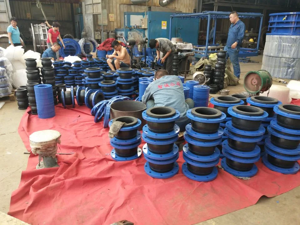
Product Photos
Technical Datasheet
KDF High-Pressure Single Sphere Rubber Expansion Joint
Technical Datasheet · PDF