
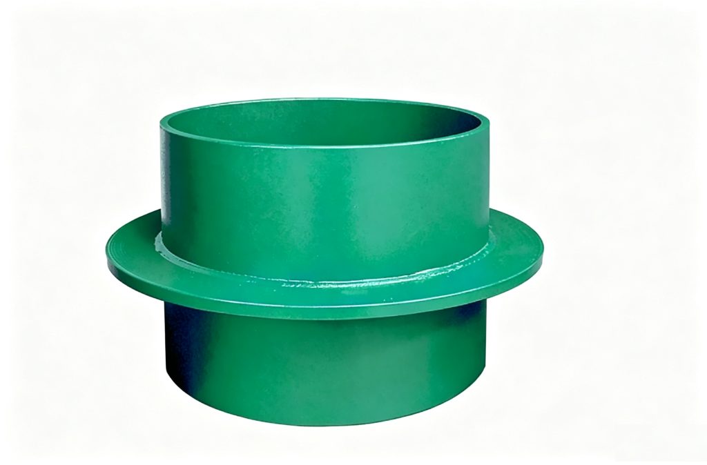
Waterproof & Sealed Wall Sleeves
02S404 Rigid Waterproof Sleeve
Mingchao’s 02S404 rigid waterproof sleeve is a cast-in wall-penetration component for concrete structures where the pipe penetration is not intended to accommodate vibration or expansion movement. The sleeve uses an external wing ring / water-stop geometry to control the seepage path at the concrete interface, while the annular space around the carrier pipe is completed according to the approved project sealing detail. Mingchao Catalog p36 documents Type A and Type B configurations.
Rigid Wall Sleeve with Water-Stop Ring
- Model / Design Atlas
- 02S404
- Product Type
- Rigid Waterproof Wall Sleeve
- Catalog Configurations
- Type A / Type B
- Type A Application
- Steel Carrier Pipe
- Type B Application
- Cast / Ductile-Iron Carrier Pipe
- Type A Reference Range
- DN50–DN2000
- Type B Reference Range
- DN75–DN1200
- 02S404 Wall Thickness
- L ≥ 200 mm
- Movement Function
- Rigid / No Movement Compensation
- Selection Basis
- Carrier Pipe + Wall Thickness + Project Detail
Project Configuration
Mingchao can customize the product configuration based on the technical information, operating conditions and dimensional data you provide. Final configuration can be reviewed and manufactured to the approved project drawing.
02S404 Rigid Waterproof Sleeve — Product Overview
The 02S404 rigid waterproof sleeve is a cast-in pipe-penetration component for concrete walls and structures where the penetration itself is not intended to absorb pipe vibration, thermal movement or expansion deformation.
The assembly places a sleeve through the wall and uses an external wing ring or water-stop feature at the sleeve-to-concrete interface. This increases the seepage path around the embedded sleeve and anchors the penetration geometry within the concrete.
Mingchao’s current Catalog p36 documents Type A and Type B configurations. Type A is used with steel carrier-pipe conditions, while Type B addresses cast-iron and ductile-iron carrier-pipe conditions defined by the 02S404 dimensional system.
Final selection must confirm the carrier-pipe outside diameter, wall thickness, selected type, waterproofing condition and project drawing.
How the Water-Stop Ring Seals the Concrete Interface
The water-stop or wing ring is welded or formed around the outside of the sleeve and becomes embedded in the concrete wall.
Its purpose is to interrupt the direct seepage path that would otherwise exist along the outer surface of a plain sleeve passing through concrete. The ring also helps locate and anchor the sleeve in the cast-in penetration.
This function addresses the sleeve-to-concrete interface. It should not be confused with sealing the annular gap between the carrier pipe and the inside of the sleeve.
The pipe-to-sleeve annular space still requires the filling or sealing detail specified for the actual project.
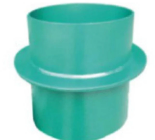
Rigid Penetration — What 02S404 rigid waterproof sleeve Does Not Accommodate
02S404 rigid waterproof sleeve is a rigid wall-penetration sleeve, not a flexible piping connector.
The 02S404 rigid-sleeve arrangement is intended for locations where the penetration is not required to accommodate pipe vibration or expansion deformation.
Do not use the rigid sleeve as an expansion joint, vibration isolator or substitute for correctly supported piping.
Where pumps, rotating equipment, seismic design conditions or thermal movement can transmit displacement toward the wall, the piping system should use the appropriate flexible connection, support and movement-control arrangement outside the rigid penetration.
02S404 Type A for Steel Pipe Penetrations
The 02S404 Type A rigid waterproof sleeve is the configuration associated with steel carrier-pipe penetrations.
The Type A dimensional relationship includes the carrier-pipe outside diameter, stop-ring geometry, sleeve outside diameter and external wing-ring diameter.
Mingchao Catalog p36 shows the Type A product configuration and its dimensional table. Because the product is identified as 02S404, the current atlas dimensional definitions are used where obvious transcription differences exist in the legacy Mingchao table.
The required sleeve length L should match the actual wall thickness rather than being selected from DN alone.
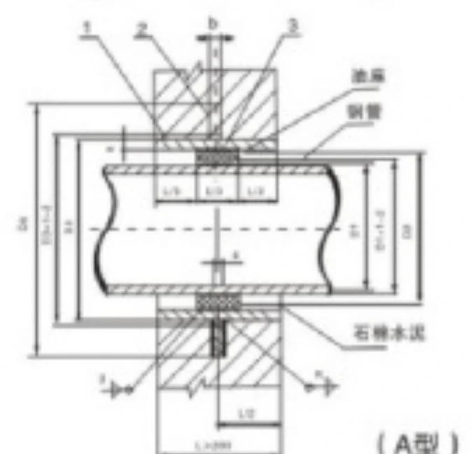
Type A Reference Dimensions — DN50–DN2000
The following Type A dimensions are taken from the 02S404 rigid waterproof-sleeve dimensional system and cross-checked against Mingchao Catalog p36. Reference weights correspond to the atlas reference sleeve length L = 200 mm. If the project wall is thicker, fabrication length and weight must be recalculated. Dimension legend: D1 — Steel carrier-pipe outside diameter; D2 — Stop-ring outside diameter; D3 — Sleeve outside diameter; D4 — Wing-ring / water-stop outside diameter; δ — Sleeve wall thickness; b — Wing-ring thickness; k — Weld size; Weight — 02S404 reference weight at L = 200 mm.
| DN | D1 — Steel Pipe OD (mm) | D2 — Stop-Ring OD (mm) | D3 — Sleeve OD (mm) | D4 — Wing-Ring OD (mm) | δ — Sleeve Wall (mm) | b — Wing-Ring Thickness (mm) | k — Weld Size (mm) | Reference Weight at L=200 (kg) |
|---|---|---|---|---|---|---|---|---|
| 50 | 60 | 80 | 114 | 225 | 3.5 | 10 | 4 | 4.49 |
| 65 | 75.5 | 95 | 121 | 230 | 3.75 | 10 | 4 | 4.66 |
| 80 | 89 | 110 | 140 | 250 | 4 | 10 | 4 | 5.33 |
| 100 | 108 | 130 | 159 | 270 | 4.5 | 10 | 5 | 6.36 |
| 125 | 133 | 155 | 180 | 290 | 6 | 10 | 6 | 8.33 |
| 150 | 159 | 180 | 219 | 330 | 6 | 10 | 6 | 10.06 |
| 200 | 219 | 240 | 273 | 385 | 8 | 12 | 8 | 15.90 |
| 250 | 273 | 295 | 325 | 435 | 8 | 12 | 8 | 18.68 |
| 300 | 325 | 345 | 377 | 500 | 10 | 14 | 10 | 27.40 |
| 350 | 377 | 400 | 426 | 550 | 10 | 14 | 10 | 30.95 |
| 400 | 426 | 445 | 480 | 600 | 10 | 14 | 10 | 34.35 |
| 450 | 480 | 500 | 530 | 650 | 10 | 14 | 10 | 37.85 |
| 500 | 530 | 550 | 590 | 730 | 10 | 16 | 10 | 44.54 |
| 600 | 630 | 660 | 690 | 830 | 10 | 16 | 10 | 54.50 |
| 700 | 720 | 750 | 790 | 920 | 10 | 16 | 10 | 61.43 |
| 800 | 820 | 850 | 880 | 1020 | 10 | 16 | 10 | 69.12 |
| 900 | 920 | 950 | 980 | 1120 | 10 | 16 | 10 | 76.81 |
| 1000 | 1020 | 1050 | 1080 | 1230 | 10 | 16 | 10 | 84.50 |
| 1200 | 1220 | 1250 | 1290 | 1430 | 12 | 20 | 12 | 122.5 |
| 1400 | 1420 | 1450 | 1490 | 1630 | 12 | 20 | 12 | 141.3 |
| 1600 | 1620 | 1650 | 1690 | 1830 | 14 | 20 | 14 | 176.4 |
| 1800 | 1820 | 1850 | 1900 | 2040 | 16 | 20 | 16 | 216.6 |
| 2000 | 2020 | 2050 | 2100 | 2240 | 16 | 20 | 16 | 239.3 |
Reference weights are based on L = 200 mm. Final sleeve length and weight must be confirmed against the actual wall thickness.
02S404 Type B for Cast / Ductile-Iron Pipe Conditions
The Type B table uses separate D1 references for cast-iron and ductile-iron carrier pipes where the 02S404 source provides both values.
This is an important difference from Type A: the selected nominal size must still be checked against the actual outside diameter and material of the carrier pipe.
Where the atlas does not provide one of the two D1 values, the value remains blank rather than being generated from the adjacent pipe series.
Final Type B selection should therefore identify whether the passing pipe is cast iron, ductile iron or another material and provide its actual outside diameter.
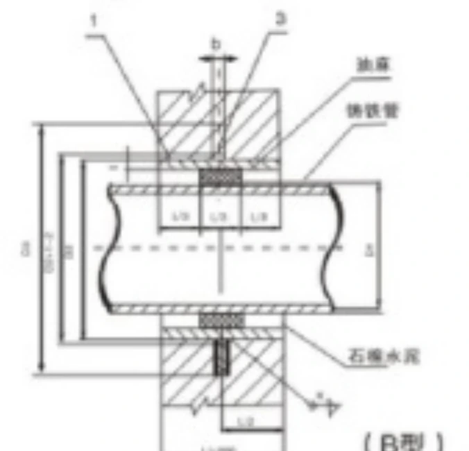
Type B Reference Dimensions — DN75–DN1200
The table below publishes the current 02S404 Type B reference dimensions used for preliminary selection.
Legacy Mingchao p36 contains several transcription differences in the Type B table. The current 02S404 atlas values are used for the locked fields below, and no additional values are inferred.
Reference weights are based on L = 200 mm and must be recalculated when the required sleeve length changes.
| DN | D1 — Cast-Iron Pipe OD (mm) | D1 — Ductile-Iron Pipe OD (mm) | D2 — Sleeve OD (mm) | D3 — Wing-Ring OD (mm) | δ (mm) | b (mm) | k (mm) | Reference Weight at L=200 (kg) |
|---|---|---|---|---|---|---|---|---|
| 75 | 93 | — | 140 | 250 | 4 | 10 | 4 | 5.33 |
| 100 | 118 | 118 | 168 | 280 | 4.5 | 10 | 5 | 6.72 |
| 150 | 169 | 170 | 219 | 330 | 6 | 10 | 6 | 10.06 |
| 200 | 220 | 220 | 273 | 385 | 8 | 12 | 8 | 15.90 |
| 250 | 271.6 | 274 | 325 | 435 | 8 | 12 | 8 | 18.68 |
| 300 | 322.8 | 326 | 377 | 500 | 10 | 14 | 10 | 27.40 |
| 350 | 374 | 378 | 426 | 550 | 10 | 14 | 10 | 30.98 |
| 400 | 425.6 | 429 | 480 | 600 | 10 | 14 | 10 | 34.35 |
| 450 | 476.8 | — | 530 | 650 | 10 | 14 | 10 | 37.85 |
| 500 | 528 | 532 | 590 | 730 | 10 | 16 | 10 | 44.54 |
| 600 | 630.8 | 635 | 690 | 830 | 10 | 16 | 10 | 54.50 |
| 700 | 733 | 738 | 790 | 930 | 10 | 16 | 10 | 62.19 |
| 800 | 836 | 842 | 900 | 1040 | 10 | 16 | 10 | 70.65 |
| 900 | 939 | 945 | 1000 | 1140 | 10 | 16 | 10 | 78.34 |
| 1000 | 1041 | 1048 | 1100 | 1240 | 10 | 16 | 10 | 104.7 |
| 1100 | 1144 | — | 1200 | 1340 | 12 | 20 | 12 | 114.1 |
| 1200 | 1246 | 1255 | 1310 | 1450 | 12 | 20 | 12 | 124.4 |
Reference weights are based on L = 200 mm. Final sleeve length and weight must be confirmed against the actual wall thickness.
Annular Gap Filling & Pipe-to-Sleeve Sealing
The rigid sleeve and its water-stop ring address the concrete penetration, but the annular space between the carrier pipe and sleeve still requires an approved project detail.
Unlike the 02S404 flexible waterproof sleeve flexible waterproof sleeve, 02S404 rigid waterproof sleeve does not use the same built-in compressed sealing-ring and gland arrangement.
The annular space may be completed with a project-specified compliant filling, sealant or mechanical sealing system depending on the carrier pipe, water exposure, maintenance requirement and local regulations.
Legacy material callouts from older drawings should not be automatically reproduced on a current international project. The project specification and applicable health, environmental and material requirements take precedence.
Wall Thickness, Concrete Placement & Cast-In Installation
The 02S404 rigid-sleeve detail uses a reference wall thickness L of at least 200 mm.
The sleeve should be positioned and secured before the concrete pour so that its axis, elevation and wall position remain stable during casting. The water-stop ring should remain properly embedded in the concrete rather than being placed at an edge where concrete coverage is inadequate.
Where the original penetration location is not a concrete wall, the penetration zone should be locally designed as a concrete section and the sleeve cast into that section according to the approved structural detail.
The local concrete zone around the wing-ring geometry must follow the 02S404/project detail. Do not use the mistranslated legacy wording that describes this requirement as a multiple of the diameter.
Seismic, Pump & Vibration Boundary Conditions
A rigid waterproof sleeve should not be relied on to absorb movement transmitted by pumps, rotating equipment or thermally expanding piping.
The 02S404 guidance states that where rigid sleeves are used in structures with seismic-fortification requirements, a suitable flexible connection should be arranged near the pipe entering the pool wall or building exterior wall.
The exact flexible connector, anchor, guide and support arrangement belongs to the piping-system design and is not part of the 02S404 rigid waterproof sleeve itself.
When the penetration is close to equipment, include the equipment location and piping-support arrangement in the RFQ.
Rigid vs. Flexible 02S404 Waterproof Sleeve
02S404 rigid waterproof sleeve and 02S404 flexible waterproof sleeve solve related wall-penetration problems but use different sealing concepts.
02S404 rigid waterproof sleeve is rigid. It is intended for penetrations that are not required to accommodate pipe vibration or expansion deformation. Its external water-stop geometry controls the concrete-interface seepage path, while the carrier-pipe annular space is completed according to the project detail.
02S404 flexible waterproof sleeve uses the 02S404 flexible waterproof-sleeve arrangement with a sealing ring and gland assembly around the carrier pipe and is selected where stricter flexible sealing, vibration or pipe deformation must be considered.
Do not select between 02S404 flexible waterproof sleeve and 02S404 rigid waterproof sleeve from nominal diameter alone.
See the 02S404 Flexible Waterproof Sleeve.
02S404 02S404 rigid waterproof sleeve vs. International Wall Sleeves with Waterstops
International project specifications commonly use terms such as steel wall sleeve, wall sleeve with waterstop, cast-in wall sleeve, puddle-flange sleeve and pipe penetration sleeve.
These products share the general principle of creating a controlled cast-in opening and interrupting water migration along the sleeve-to-concrete interface.
Many international systems pair the wall sleeve with a separate modular or press seal around the carrier pipe. 02S404 rigid waterproof sleeve instead follows the 02S404 rigid waterproof-sleeve dimensional and installation concept.
The systems are related in function but are not dimensionally interchangeable. If the project is specified around a Link-Seal-type, press-seal or other proprietary system, send that specification rather than substituting 02S404 rigid waterproof sleeve automatically.
Applications in Water, Wastewater & Building Penetrations
Typical 02S404 rigid waterproof sleeve project contexts include concrete wall penetrations in civil and industrial buildings, municipal water and wastewater structures, basements, utility rooms, tanks and other structures where the penetration requires a defined water-stop sleeve but is not intended to accommodate pipeline movement.
02S404 rigid waterproof sleeve can also be considered for steel, cast-iron or ductile-iron carrier-pipe conditions according to the selected 02S404 type.
These are application contexts rather than universal waterproof-pressure approvals. Groundwater level, water head, corrosive exposure, drinking-water requirements, carrier-pipe service and the structural wall detail must be reviewed for each project.
How to Specify 02S404 rigid waterproof sleeve for Quotation
Start with the required 02S404 type and the material and actual outside diameter of the carrier pipe.
Then provide the nominal size, wall thickness L, penetration location, water-facing side and the required waterproofing condition.
Confirm whether the penetration is exposed to groundwater or defined water head and whether pumps, vibration, seismic requirements or thermal movement exist near the wall.
Also identify the required sleeve material, coating or corrosion-protection system, annular filling or sealing specification, potable-water requirement if applicable, inspection documents and the project wall-penetration drawing.
For accurate selection, send the 02S404 Type A/B requirement, carrier-pipe material and outside diameter, wall thickness, waterproofing condition and project penetration drawing. If groundwater, vibration, corrosion protection or a specific annular sealing detail applies, include those requirements as well.
- 02S404 requirement / project reference
- Type A / Type B / not yet specified
- Carrier-pipe material — Steel / Cast Iron / Ductile Iron / Other
- DN
- Actual carrier-pipe OD
- Wall thickness L
- Concrete wall / structure type
- Penetration location
- Water-facing side / orientation
- Waterproofing requirement
- Groundwater / external water-head condition
- Any vibration at penetration
- Nearby pump / rotating equipment
- Expected pipe thermal movement / deformation
- Nearby flexible-connection arrangement if specified
- Sleeve material requirement
- Wing-ring / water-stop requirement
- Surface coating / corrosion protection
- Corrosive groundwater / environment
- Annular filling / sealing specification
- Potable-water requirement if relevant
- Carrier-pipe service / medium
- Installation orientation
- Quantity
- Destination
- Inspection / welding / material documentation
- Project penetration drawing
Product Photo, Type A/B Drawings & Project RFQ
Final production should follow the approved carrier-pipe dimensions, wall thickness, selected 02S404 type, water exposure, corrosion-protection requirements and project drawing.
The annular filling and sealing system between carrier pipe and sleeve must follow the approved project detail and current local material, health and environmental requirements.
Steel/cast components, coating and corrosion protection are confirmed against the selected 02S404 type and project specification.
Technical Datasheet
02S404 Rigid Waterproof Sleeve
Technical Datasheet · PDF