
Rubber Expansion Joints
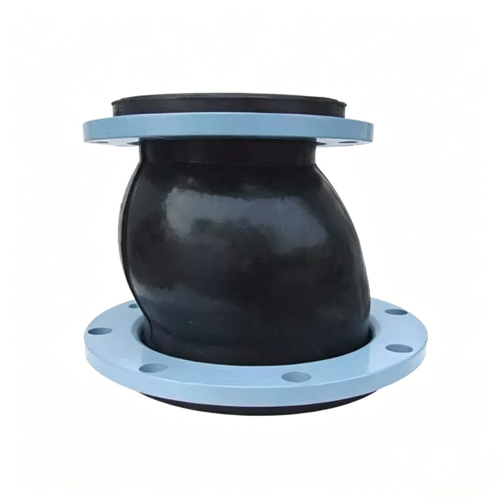
JGD (KXT) Eccentric Reducing Rubber Expansion Joint
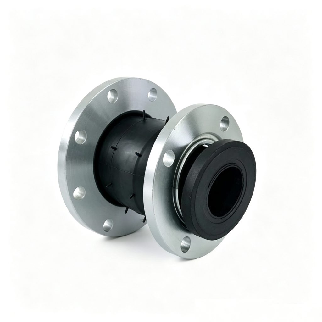
The Mingchao JGD (KXT) Eccentric Reducing Rubber Expansion Joint combines a flexible rubber connector with an unequal-size transition and an offset centerline. It is intended for piping layouts where different nominal pipe sizes must be connected while maintaining a defined eccentric orientation and providing vibration isolation and controlled movement accommodation.
JGD (KXT) · ECCENTRIC REDUCER · CUSTOM TO DRAWING
- Model
- JGD (KXT)
- Connection Geometry
- Eccentric / Unequal Size
- Catalog Combinations
- 48
- Catalog Pair Range
- DN50 × DN32 to DN600 × DN500
- Catalog Face-to-Face
- 180–240 mm, size-dependent
- Movement
- Axial / Lateral / Angular, size-dependent
- Customization
- Drawing-Based
Project Configuration
Mingchao can customize the product configuration based on the technical information, operating conditions and dimensional data you provide. Final configuration can be reviewed and manufactured to the approved project drawing.
JGD (KXT) Eccentric Reducing Rubber Expansion Joint — Overview
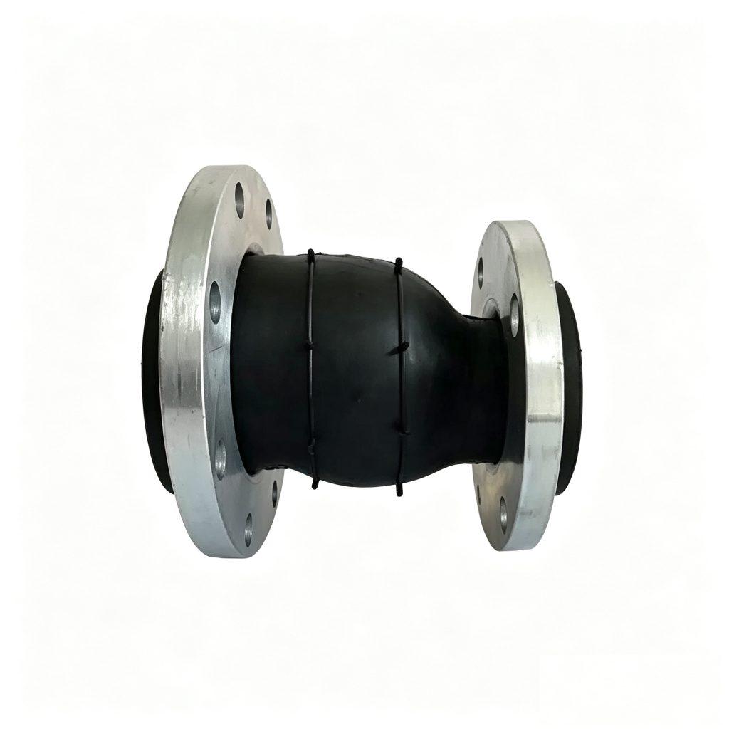
The JGD (KXT) eccentric reducing rubber expansion joint combines an unequal-size transition with a flexible reinforced-rubber body. The large and small connections are intentionally offset rather than positioned on one common centerline. This makes orientation an engineering input, not merely an installation detail.
An eccentric reducing rubber expansion joint connects two different nominal pipe sizes while the two connection centerlines are intentionally offset. The reinforced rubber body also provides flexible isolation and configuration-specific movement capability.
Mingchao’s catalog provides 48 reference size combinations from DN50 × DN32 to DN600 × DN500. Non-catalog diameter combinations, face-to-face lengths, flange drilling, eccentric orientation and other principal dimensions can be manufactured to approved customer or project drawings.
Why Eccentric Geometry Matters for Unequal Pipe Sizes
Unlike a concentric reducing joint, the large and small ends of an eccentric reducer do not share the same centerline. The offset geometry allows the transition to follow a defined piping elevation or flat-side orientation. The required eccentric direction must therefore be identified before manufacture and installation.
Eccentric geometry must not be interpreted as permission to pull misaligned piping into position with the joint.
Eccentric vs. Concentric Reducing Rubber Expansion Joints
A concentric reducer keeps both connection centerlines aligned. An eccentric reducer offsets them, so the required orientation must be defined from the piping layout or approved drawing.
| Product | Geometry | Centerlines | Orientation | Selection |
|---|---|---|---|---|
| JDX concentric configuration JDX | Concentric | Aligned | Rotationally symmetric transition | Centered unequal-size transition |
| JGD (KXT) eccentric configuration JGD (KXT) | Eccentric | Offset | Direction must be defined | Unequal-size transition where offset geometry is required |
Both configurations may be manufactured to approved project drawings.
Reinforced Rubber Body & Construction
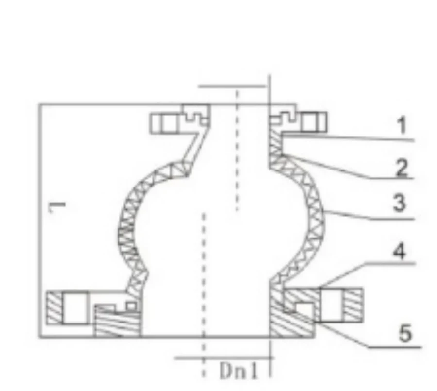
The documented JGD (KXT) eccentric configuration construction uses inner and outer rubber layers, nylon reinforcement, metal flanges and a steel reinforcing wire ring. Material selection is not independent of service conditions: the medium, temperature, pressure, flange environment and project requirements must be reviewed together before final manufacture.
| Component | Catalog Material Reference |
|---|---|
| Outer Rubber Layer | IIR / CR / EPDM / NR / NBR |
| Inner Rubber Layer | IIR / CR / EPDM / NR / NBR |
| Nylon Reinforcement | Nylon |
| Flange | Q235 / 304 / 316L |
| Steel Reinforcing Wire Ring | Steel |
The catalog materials above are reference configurations. Final rubber compound, flange material, reinforcement and corrosion-protection requirements are selected for the project, service medium and approved drawing.
JGD (KXT) Catalog Size & Movement Data
Catalog reference combinations are shown from DN50 × DN32 to DN600 × DN500. Non-catalog diameter combinations and principal dimensions can be manufactured to approved customer or project drawings.
| Large DN × Small DN | Face-to-Face L (mm) | Axial Extension (mm) | Axial Compression (mm) | Lateral Displacement (mm) | Deflection Angle (deg) |
|---|---|---|---|---|---|
| DN50 × DN32 | 180 | 20 | 30 | 45 | 35 |
| DN50 × DN40 | 180 | 20 | 30 | 45 | 35 |
| DN65 × DN40 | 180 | 20 | 30 | 45 | 35 |
| DN65 × DN50 | 180 | 20 | 30 | 45 | 35 |
| DN80 × DN40 | 180 | 20 | 30 | 45 | 35 |
| DN80 × DN50 | 180 | 20 | 30 | 45 | 35 |
| DN80 × DN65 | 180 | 20 | 30 | 45 | 35 |
| DN100 × DN40 | 180 | 20 | 30 | 45 | 35 |
| DN100 × DN50 | 180 | 20 | 30 | 45 | 35 |
| DN100 × DN65 | 180 | 22 | 30 | 45 | 35 |
| DN100 × DN80 | 180 | 22 | 30 | 45 | 35 |
| DN125 × DN50 | 200 | 22 | 30 | 45 | 35 |
| DN125 × DN65 | 200 | 22 | 30 | 45 | 35 |
| DN125 × DN80 | 200 | 22 | 30 | 45 | 35 |
| DN125 × DN100 | 200 | 22 | 30 | 45 | 35 |
| DN150 × DN50 | 200 | 22 | 30 | 45 | 35 |
| DN150 × DN65 | 200 | 22 | 30 | 45 | 35 |
| DN150 × DN80 | 200 | 22 | 30 | 45 | 35 |
| DN150 × DN100 | 200 | 22 | 30 | 45 | 35 |
| DN150 × DN125 | 200 | 22 | 30 | 45 | 35 |
| DN200 × DN80 | 200 | 22 | 30 | 40 | 30 |
| DN200 × DN100 | 200 | 22 | 30 | 40 | 30 |
| DN200 × DN125 | 200 | 25 | 30 | 40 | 30 |
| DN200 × DN150 | 200 | 25 | 35 | 40 | 30 |
| DN250 × DN125 | 220 | 25 | 35 | 40 | 30 |
| DN250 × DN150 | 220 | 25 | 35 | 40 | 30 |
| DN250 × DN200 | 220 | 25 | 35 | 40 | 30 |
| DN300 × DN125 | 220 | 25 | 35 | 40 | 30 |
| DN300 × DN150 | 220 | 25 | 35 | 40 | 30 |
| DN300 × DN200 | 220 | 25 | 35 | 40 | 30 |
| DN300 × DN250 | 220 | 25 | 35 | 40 | 30 |
| DN350 × DN150 | 240 | 25 | 35 | 40 | 30 |
| DN350 × DN200 | 240 | 28 | 38 | 35 | 26 |
| DN350 × DN250 | 240 | 28 | 38 | 35 | 26 |
| DN350 × DN300 | 240 | 25 | 35 | 40 | 30 |
| DN400 × DN200 | 240 | 25 | 35 | 40 | 30 |
| DN400 × DN250 | 240 | 28 | 38 | 40 | 30 |
| DN400 × DN300 | 240 | 28 | 38 | 40 | 30 |
| DN400 × DN350 | 240 | 28 | 38 | 40 | 30 |
| DN450 × DN300 | 240 | 28 | 38 | 40 | 30 |
| DN450 × DN350 | 240 | 28 | 38 | 40 | 30 |
| DN450 × DN400 | 240 | 28 | 38 | 40 | 30 |
| DN500 × DN350 | 240 | 28 | 38 | 40 | 30 |
| DN500 × DN400 | 240 | 28 | 38 | 40 | 30 |
| DN500 × DN450 | 240 | 28 | 38 | 40 | 30 |
| DN600 × DN400 | 240 | 28 | 38 | 40 | 30 |
| DN600 × DN450 | 240 | 28 | 38 | 40 | 30 |
| DN600 × DN500 | 240 | 28 | 38 | 40 | 30 |
Movement values are size-specific catalog references. Maximum axial, lateral and angular movements must not be assumed to occur simultaneously. Final allowable movement and operating conditions must be confirmed for the selected product configuration and project.
Large-End × Small-End Sizing & Eccentric Orientation
JGD (KXT) eccentric configuration must be specified with two nominal sizes. For example, DN200 × DN150 identifies the large-end and small-end nominal sizes of one eccentric reducing joint; it is not a single DN200 joint. The required eccentric direction should also be identified on the piping or fabrication drawing.
For replacement work, provide the existing face-to-face dimension, both connection dimensions and the required orientation instead of selecting by nominal size alone.
How is an JGD (KXT) eccentric configuration size specified? Specify both ends, for example DN200 × DN150, together with the required eccentric orientation and flange details.
Custom Engineering Specification Matrix
Use these RFQ fields to define catalog or custom geometry without assuming unsupported performance values. Approved drawings govern final geometry.
| Engineering / RFQ Field | Required Treatment |
|---|---|
| Large-End Nominal Diameter | Catalog reference where available; custom to approved drawing |
| Small-End Nominal Diameter | Catalog reference where available; custom to approved drawing |
| Eccentric Direction | Project-specific; approved drawing governs final configuration |
| Required Flat-Side / Offset Orientation | Project-specific; approved drawing governs final configuration |
| Face-to-Face Length | Catalog reference where available; custom to approved drawing |
| End A Flange Standard | Project-specific; approved drawing governs final configuration |
| End B Flange Standard | Project-specific; approved drawing governs final configuration |
| End A Flange Drilling | Project-specific; approved drawing governs final configuration |
| End B Flange Drilling | Project-specific; approved drawing governs final configuration |
| Flange Material | Project-specific; approved drawing governs final configuration |
| Rubber Compound | Project-specific; approved drawing governs final configuration |
| Reinforcement Requirement | Project-specific; approved drawing governs final configuration |
| Working Pressure | Project-specific; factory confirmation required |
| Test Requirement | Project-specific; factory confirmation required |
| Vacuum Requirement | Project-specific; factory confirmation required |
| Axial Movement Requirement | Catalog reference where available; custom to approved drawing |
| Lateral Movement Requirement | Catalog reference where available; custom to approved drawing |
| Angular Movement Requirement | Catalog reference where available; custom to approved drawing |
| Medium / Fluid | Project-specific; approved drawing governs final configuration |
| Operating Temperature | Project-specific; factory confirmation required |
| Flow Direction | Project-specific; approved drawing governs final configuration |
| Control / Limit Rod Requirement | Project-specific; approved drawing governs final configuration |
| Quantity | Project-specific; approved drawing governs final configuration |
| Customer Drawing / CAD | Required or strongly recommended for custom/replacement configurations |
Can Mingchao manufacture sizes not shown in the table? Yes. Mingchao can manufacture non-catalog diameter combinations, face-to-face lengths, eccentric orientations, flange drilling and other principal dimensions to approved customer or project drawings.
Independent Flange Configuration at Both Ends
End A and End B should be treated as independent connection interfaces during quotation. Flange standard, drilling pattern, material and connection geometry can be reviewed separately for each end when required by the project. The approved customer or project drawing governs the final manufacturing dimensions.
GB / PN, EN / DIN, JIS and ANSI / ASME are common international project terms; the requested standard and exact drilling must be confirmed rather than assumed as stock.
Can the two ends use different flange configurations? Yes. End A and End B can be reviewed independently for flange standard, drilling, material and project connection requirements, subject to the approved drawing.
Rubber Compound & Service-Medium Selection
The JGD (KXT) eccentric configuration catalog identifies IIR, CR, EPDM, NR and NBR as rubber-material references. Final compound selection should be based on the actual fluid, concentration where relevant, operating temperature, pressure, cleaning chemicals and other service conditions.
Where a project requires a compound or material configuration outside the catalog reference, Mingchao can review the requirement as a drawing-based custom configuration.
Movement, Pressure, Vacuum & Temperature — Project Verification
Pressure, vacuum, temperature and movement capability are configuration-dependent. They are influenced by the selected diameter pair, rubber compound, reinforcement, face-to-face length, flange arrangement and operating conditions. A flange class alone does not establish the allowable operating pressure of the complete rubber expansion joint.
Vacuum service must be identified during quotation. Do not assume positive-pressure catalog information establishes negative-pressure capability.
The catalog axial, lateral and angular values are reference values for individual size configurations. Their maximum values must not be combined simultaneously unless the approved engineering configuration specifically permits it.
Are pressure, temperature and movement values universal? No. Allowable pressure, temperature, vacuum and movement depend on the selected configuration and operating conditions and must be confirmed for the project.
Pump, Equipment & Horizontal Pipeline Applications
Eccentric reducing rubber expansion joints may be considered in horizontal piping, pump connections, equipment transitions and other systems where an unequal-size connection and a defined offset are required. The final eccentric orientation, flow arrangement, supports, anchors and equipment requirements remain part of the piping-system design.
The product is not represented as preventing cavitation or water hammer, guaranteeing pump protection, carrying equipment load or correcting pipe misalignment.
Installation — Orientation, Alignment & No Torsion
- Confirm large end and small end before installation.
- Confirm required eccentric direction before bolting.
- Verify both flange standards and drilling patterns.
- Align mating flanges without forcing the rubber joint into position.
- Do not use flange bolts to pull misaligned piping together.
- Do not install under torsional preload.
- Do not twist the eccentric body to correct orientation.
- Support pipe and equipment weight independently.
- Use anchors and guides according to the piping-system design.
- Control / limit rods are project/system dependent.
- Tighten bolting progressively and evenly.
- Recheck orientation after installation.
- Confirm pressure, vacuum, temperature and medium before commissioning.
Can the joint support pipe weight? No. Pipe and equipment weight should be supported by the piping system rather than imposed on the rubber expansion joint.
Can the eccentric joint be twisted during installation? No. The required orientation should be established before bolting, and the rubber body should not be installed under torsional preload.
Relevant Chinese Product References
GB/T 26121-2010 可曲挠橡胶接头, HG/T 2289-2017 可曲挠橡胶接头 and CJ/T 208-2005 可曲挠橡胶接头 are relevant Chinese technical references for flexible rubber joints.
These standards are relevant Chinese technical references for flexible rubber joints. The specific standard, inspection requirements and acceptance criteria applicable to an JGD (KXT) eccentric configuration order must be confirmed in the purchase specification or approved project documentation. No universal compliance or product certification is claimed.
How to Specify JGD (KXT) eccentric configuration for Quotation
For an JGD (KXT) eccentric configuration quotation, provide the large-end DN, small-end DN, required eccentric orientation, flange standard and drilling at both ends, face-to-face length, working pressure, operating temperature, medium, vacuum condition if applicable, movement requirement, quantity and the project or replacement drawing.
If the required size pair or principal dimensions are not listed in the catalog table, send the required drawing. Mingchao can manufacture non-catalog dimensions and geometric configurations after drawing review and approval.
Send Both Pipe Sizes & Drawing — Request a Project-Specific Engineering Quotation.
- Large-end DN
- Small-end DN
- Required eccentric orientation
- Flange standard and drilling at both ends
- Face-to-face length
- Working pressure
- Operating temperature
- Medium / concentration
- Vacuum condition if applicable
- Axial / lateral / angular movement requirement
- Control or limit rod requirement
- Quantity
- Project or replacement drawing / CAD
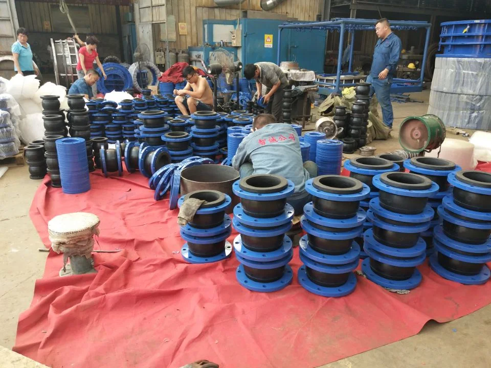
Product Photos
Technical Datasheet
JGD (KXT) Eccentric Reducing Rubber Expansion Joint
Technical Datasheet · PDF