
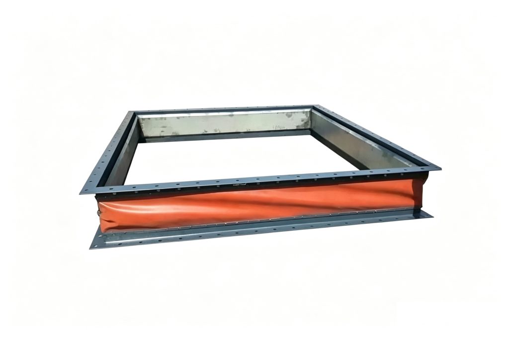
Air Duct & Fabric Expansion Joints
FUB / FVB Rubber Duct Expansion Joint
FUB / FVB rubber duct expansion joints provide a flexible connection for low-pressure air and gas ducting around fans, blowers and industrial duct systems. Mingchao's catalog shows round and rectangular configurations with rubber flexible elements and metal connection hardware. Catalog common values include a working pressure of ≤4500 Pa and an installation length of 300–450 mm; final selection should be confirmed against duct geometry, movement, temperature, gas composition and project drawings.
Rubber Duct Expansion Joint
- Models
- FUB / FVB
- Product Type
- Rubber Duct Expansion Joint
- Typical Service
- Low-Pressure Air & Gas Ducting
- Configurations
- Round & Rectangular Available
- Catalog Working Pressure
- ≤4500 Pa
- Catalog Installation Length
- 300–450 mm
- Flexible Element
- Rubber
- Selection Basis
- Project-Specific
Project Configuration
Mingchao can customize the product configuration based on the technical information, operating conditions and dimensional data you provide. Final configuration can be reviewed and manufactured to the approved project drawing.
FUB / FVB Rubber Duct Expansion Joint Overview
The FUB / FVB family is designed for flexible connections in low-pressure air and gas ducting where rigid duct sections, fans or blowers need controlled flexibility between connected components.
Unlike a conventional pressure-piping rubber expansion joint, this product family is built around duct geometry and low-pressure air or gas service. The flexible rubber element helps isolate equipment vibration and accommodate designed movement while the surrounding metal connection hardware interfaces with the duct system.
Mingchao's catalog includes both round and rectangular configurations. Final configuration should be selected from the actual duct dimensions, required movement, working pressure, temperature, medium and installation layout.
Round & Rectangular Duct Configurations
Industrial duct systems are commonly built in both round and rectangular sections. Mingchao's FUB/FVB rubber duct configuration catalog family includes product configurations for both geometries, allowing the flexible connection to be matched to the actual duct layout rather than forcing a piping-style connector into the application.
The catalog provides separate FUB and FVB connection-dimension tables. Because the source model coding includes multiple shape designations, the quotation should identify the required duct shape and dimensions in addition to the FUB or FVB model designation.
For round ducts, provide the required duct diameter and connection dimensions. For rectangular ducts, provide width, height, flange or frame dimensions and the project drawing.
Do not state that FUB always equals round or FVB always equals rectangular.
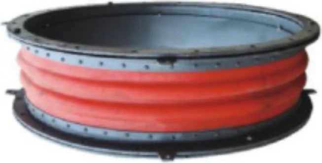
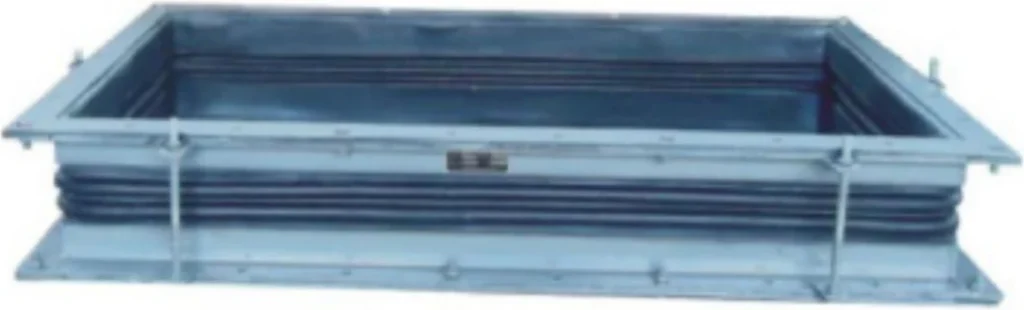
Rubber Flexible Element, Frames & Connection Hardware
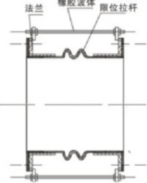
The Mingchao catalog drawings show a rubber flexible element installed between metal connection structures. Depending on the configuration, the catalog drawings also show guide, limit, adjusting, clamping or pressure-plate hardware used to control and secure the assembly.
The flexible element provides the compliant portion of the connection, while the metal interface transfers the connection into the surrounding ductwork.
Exact rubber compound, reinforcement construction, metal grade, coating and hardware configuration must be selected for the actual gas, temperature, environment and project specification. These details should not be presented as universal FUB/FVB rubber duct configuration material grades until confirmed for the quotation.
Movement, Vibration & Noise Isolation in Duct Systems
A rubber duct expansion joint provides flexibility between connected duct sections and equipment. In fan and blower systems, this flexibility can reduce the direct transmission of equipment vibration and structure-borne noise into the adjoining ductwork.
The joint can also accommodate designed duct movement and limited installation displacement within the approved configuration.
Movement capacity is not a single universal value for the entire FUB / FVB family. For the selected configuration, the required movement should be stated in the RFQ and confirmed for the selected configuration.
The flexible element must not be used as a substitute for correct duct alignment, structural support or system engineering.
Catalog Performance — Confirmed Common Values
The following values are printed identically for both configuration columns in the Mingchao catalog and can be used for preliminary selection. Configuration-specific movement and temperature limits should be confirmed during quotation.
| Parameter | Catalog Value |
|---|---|
| Catalog Working Pressure | ≤4500 Pa |
| Catalog Installation Length | 300–450 mm |
| Stretch-Length Change Rate | ≤15% |
Variant-specific movement, temperature and support-spacing values must be confirmed for the selected configuration and project requirements.
FUB Connection Dimensions
The FUB connection table below is transcribed from Mingchao Catalog printed page 32 for preliminary dimensional reference. Dimensions are shown in millimetres and weight in kilograms.
Confirm the FUB1100 D1 value against the approved project data before ordering. No value has been interpolated or substituted.
Final connection dimensions should be checked against the approved project drawing before manufacturing.
| Model | D (mm) | D1 (mm) | D2 (mm) | D3 (mm) | Weight (kg) |
|---|---|---|---|---|---|
| FUB800 | 812 | 950 | 1000 | 850 | 184.6 |
| FUB900 | 912 | 1050 | 1100 | 950 | 203.6 |
| FUB1000 | 1012 | 1150 | 1200 | 1052 | 221.9 |
| FUB1100 | 1112 | 1300 | 1152 | 240.7 | |
| FUB1200 | 1212 | 1320 | 1400 | 1252 | 259.5 |
| FUB1300 | 1312 | 1450 | 1500 | 1352 | 278.3 |
| FUB1400 | 1412 | 1550 | 1600 | 1452 | 357.3 |
| FUB1500 | 1512 | 1650 | 1700 | 1552 | 391.2 |
| FUB1600 | 1614 | 1750 | 1800 | 1654 | 426.3 |
| FUB1700 | 1714 | 1850 | 1900 | 1751 | 449.7 |
| FUB1800 | 1814 | 1950 | 2000 | 1854 | 481.0 |
| FUB1900 | 1914 | 2050 | 2120 | 1954 | 533.4 |
| FUB2000 | 2016 | 2170 | 2240 | 2056 | 619.9 |
| FUB2100 | 2116 | 2270 | 2340 | 2156 | 753.3 |
| FUB2200 | 2216 | 2370 | 2440 | 2256 | 785.3 |
| FUB2300 | 2316 | 2470 | 2540 | 2356 | 817.2 |
| FUB2400 | 2416 | 2570 | 2640 | 2456 | 800.2 |
| FUB2500 | 2516 | 2670 | 2740 | 2556 | 881.2 |
| FUB2600 | 2616 | 2770 | 2840 | 2656 | 913.2 |
| FUB2800 | 2816 | 2970 | 3040 | 2856 | 986.5 |
| FUB3000 | 3016 | 3170 | 3240 | 3056 | 1050.5 |
| FUB3200 | 3216 | 3370 | 3440 | 3256 | 1114.6 |
FVB Connection Dimensions
The FVB connection table is taken from Mingchao Catalog printed page 32. Only source-confirmed dimensional cells are published.
Confirm the affected FVB model label and D values for FVB2200 and FVB3000 against the approved project data before ordering. Confirm the FVB3200 D2 value against the approved project data before ordering.
The table is intended for preliminary selection; final manufacturing dimensions should be confirmed against the project drawing.
| Model | D (mm) | D1 (mm) | D2 (mm) | D3 (mm) | Weight (kg) |
|---|---|---|---|---|---|
| FVB500 | 529 | 600 | 640 | 469 | 89.8 |
| FVB600 | 630 | 705 | 755 | 570 | 114.6 |
| FVB700 | 720 | 810 | 860 | 660 | 134.8 |
| FVB800 | 820 | 920 | 975 | 760 | 192.0 |
| FVB1000 | 1020 | 1120 | 1175 | 960 | 241.6 |
| FVB1100 | 1120 | 1220 | 1275 | 1060 | 263.0 |
| FVB1200 | 1220 | 1320 | 1375 | 1160 | 312.6 |
| FVB1300 | 1320 | 1420 | 1475 | 1260 | 335.0 |
| FVB1400 | 1420 | 1520 | 1575 | 1360 | 369.6 |
| FVB1500 | 1520 | 1630 | 1685 | 1440 | 349.4 |
| FVB1600 | 1620 | 1730 | 1785 | 1540 | 477.5 |
| FVB1700 | 1720 | 1830 | 1985 | 1640 | 515.9 |
| FVB1800 | 1820 | 1930 | 2085 | 1740 | 536.0 |
| FVB1900 | 1920 | 2030 | 2185 | 1840 | 565.2 |
| FVB2000 | 2000 | 2130 | 2410 | 1940 | 725.2 |
| FVB2200 | 2340 | 2610 | 2140 | 881.8 | |
| FVB2400 | 2420 | 2540 | 2710 | 2340 | 953.0 |
| FVB2500 | 2520 | 2640 | 2810 | 2440 | 1057.5 |
| FVB2600 | 2620 | 2760 | 3030 | 2540 | 1098.4 |
| FVB2800 | 2820 | 2960 | 3230 | 2740 | 1260.9 |
| FVB3000 | 3160 | 3430 | 2940 | 1347.8 | |
| FVB3200 | 3220 | 3360 | 3140 | 1441.5 |
Catalog note: Large-diameter air duct rubber compensators can be manufactured to customer requirements.
Fan, Blower & Industrial Duct Applications
Rubber duct expansion joints are used where industrial ductwork requires a flexible connection between rigid sections or between rotating equipment and the connected duct system.
Typical engineering contexts include:
- fan inlet and discharge connections
- blower connections
- industrial ventilation ducting
- process-air ducting
- low-pressure process-gas ducting
- dust-collection systems
- environmental-control ductwork
- power, cement and general industrial duct systems where the selected rubber construction is compatible with the actual service
These are application contexts rather than universal service approvals. Gas composition, temperature, moisture, dust, abrasion and chemical exposure must be reviewed before material selection.
Do not publish universal flue-gas suitability, a high-temperature guarantee or acid-gas compatibility unless project-specific materials are confirmed.
How to Select a Rubber Duct Expansion Joint
Selection should begin with the duct geometry and required movement rather than with a nominal pipe size.
First identify whether the duct is round, rectangular or another project-specific shape. Then provide the actual connection dimensions, required movement, available installation length and the location of the joint relative to the fan, blower or other equipment.
Operating pressure and any negative-pressure condition must be stated because duct joints can be exposed to both positive and suction service. Temperature, gas composition, moisture, dust, abrasion and corrosive constituents are also important when selecting the flexible-element construction.
Connection-frame dimensions, bolt pattern, liner or sleeve requirements, insulation and project documentation should be defined from the project drawing before manufacturing.
For accurate selection, send the duct shape and dimensions, required movement, installation length, operating pressure or vacuum, temperature, gas composition and a project drawing where available.
- Duct shape — Round / Rectangular / Other
- FUB / FVB model, if already specified
- Duct dimensions — round diameter or rectangular width × height
- Required movement / compensation
- Movement direction
- Fan / blower / equipment connection location
- Available installation / face-to-face length
- Normal operating pressure
- Design / maximum pressure
- Vacuum / negative-pressure condition
- Operating temperature
- Maximum / upset temperature
- Air / gas / medium
- Gas composition / corrosive constituents
- Moisture / condensate
- Dust / solids loading
- Abrasion condition
- Gas velocity if relevant
- Connection frame / flange dimensions
- Bolt pattern / drilling
- Metal frame material if specified
- Flexible-element material requirement if specified
- Internal liner / sleeve requirement
- Insulation requirement
- Installation orientation
- Duct support / guide arrangement
- Quantity
- Destination
- Testing / inspection / documentation
- Project drawing / duct layout
Rubber Duct Expansion Joint vs Fabric Expansion Joint
Rubber duct expansion joints and fabric expansion joints can both provide flexible connections in duct systems, but they should not be treated as interchangeable products.
A rubber duct expansion joint uses an elastomeric flexible element and is commonly selected for low-pressure fan, blower and industrial duct connections where vibration isolation and controlled movement are required.
Fabric expansion joints use layered non-metallic belt constructions and are often engineered for different temperature, movement, size and gas-service conditions.
The correct choice depends on operating temperature, pressure or vacuum, movement, duct geometry, gas composition and required material construction.
Temperature and movement limits must be confirmed for the selected configuration.
Related configurations include round and rectangular fabric expansion joints for air ducts.
Installation — Alignment, Supports & Flexible-Element Protection
Install the joint at the approved installation length and connection geometry shown on the project drawing.
The adjoining ductwork and equipment should be aligned before the flexible joint is installed. Do not use the rubber element to pull severely misaligned duct sections into position.
Support duct and equipment weight independently so the flexible element is not used as a structural support.
Protect the rubber element from sharp edges, impact, welding sparks, hot slag and construction damage.
Do not introduce torsion or uncontrolled over-extension during installation.
Where guide, limit, clamping or adjustment hardware is included in the approved configuration, do not remove or reposition it without the project drawing or engineering instruction.
Confirm whether the service includes positive pressure, negative pressure or pressure pulsation before commissioning.
Inspect the flexible element and connection hardware for visible damage, abnormal distortion and connection security before operation.
Do not publish universal bolt torque values.
Product Photos, Drawings & Project RFQ
The images below are exact FUB/FVB rubber duct configuration structural references cropped from Mingchao Catalog printed page 31.
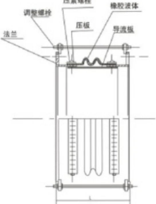
JB/T 12235-2015 is a relevant Chinese industry reference for non-metallic expansion joints. Project-specific manufacturing and documentation requirements should be confirmed during quotation.
Use the existing Air Duct & Fabric Expansion Joints Series and Technical Information for broader context. Final FUB/FVB rubber duct configuration and dimensions are confirmed from the project RFQ and drawing.
Product Photos
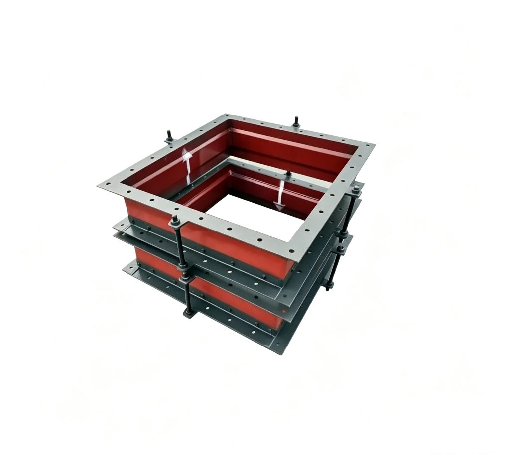
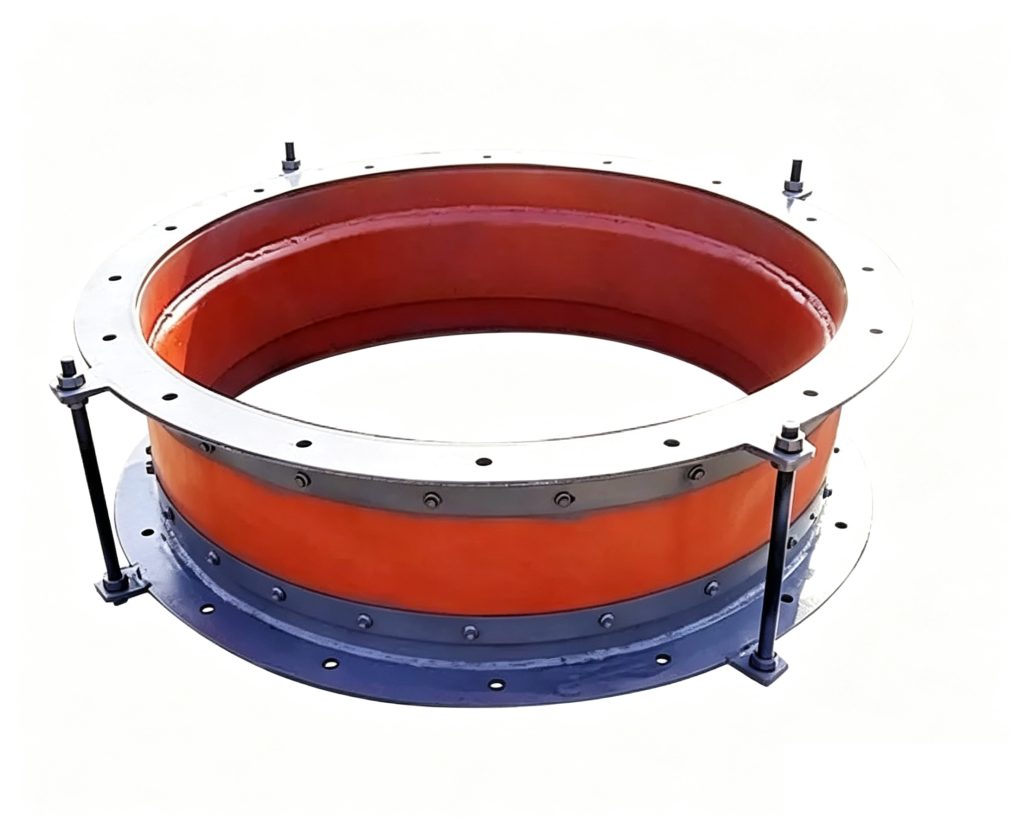
Technical Datasheet
FUB / FVB Rubber Duct Expansion Joint
Technical Datasheet · PDF