
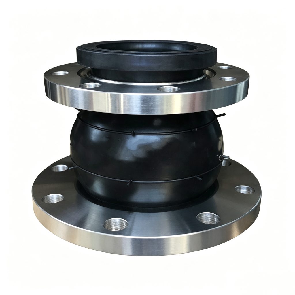
Rubber Expansion Joints
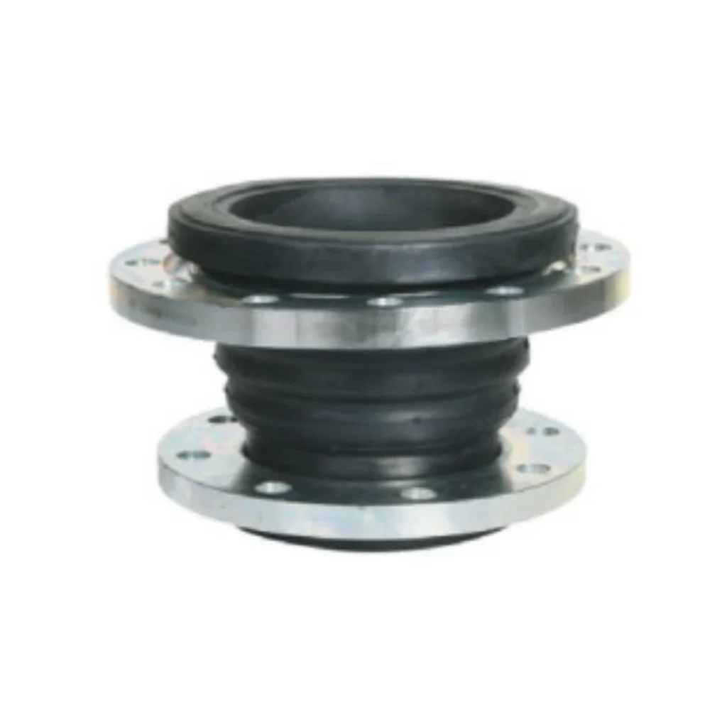
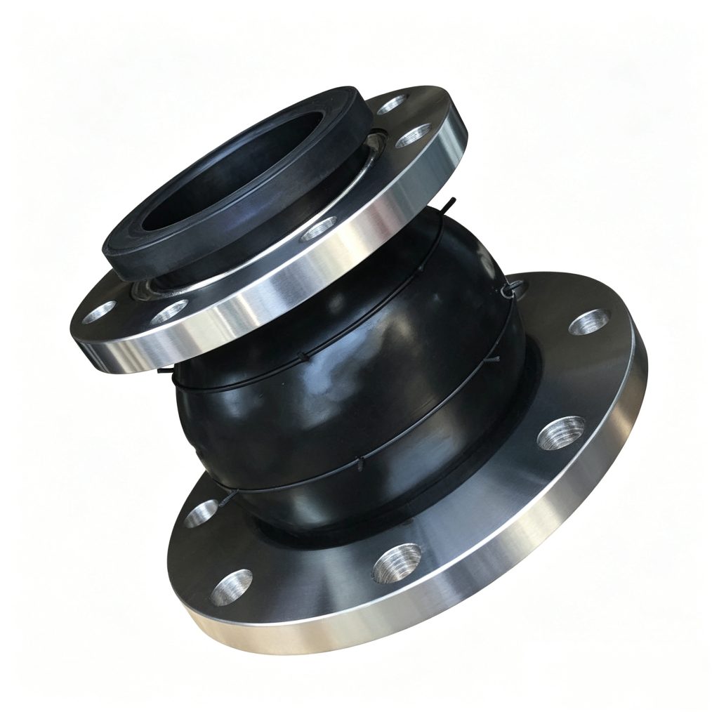
JDX Concentric Reducing Rubber Expansion Joint
The JDX Concentric Reducing Rubber Expansion Joint connects two different pipe diameters while providing a flexible interface for vibration isolation and controlled axial, lateral and angular movement. Mingchao’s catalog documents 48 DN1×DN2 combinations from DN50×DN32 through DN600×DN500. Non-standard diameter pairs, face-to-face lengths, flange drilling, elastomers and connection details can be manufactured to approved customer or project drawings.
CONCENTRIC PIPE-SIZE TRANSITION · VIBRATION ISOLATION · CUSTOM ENGINEERING
- Geometry
- Concentric
- Catalog Pair Range
- DN50×DN32 to DN600×DN500
- Catalog Combinations
- 48
- Movement
- Axial · Lateral · Angular
- Custom Engineering
- DN Pair · Length · Flanges · Materials
Stock / Fast ShipmentMany common size combinations can be prepared for faster shipment; actual availability is confirmed according to the required large-end and small-end diameters and configuration.
CustomizationCustom dimensions are available according to confirmed pipe sizes, installation length and project requirements.
Project Configuration
Mingchao can customize the product configuration based on the technical information, operating conditions and dimensional data you provide. Final configuration can be reviewed and manufactured to the approved project drawing.
JDX Concentric Reducing Rubber Expansion Joint — Product Overview
The JDX Concentric Reducing Rubber Expansion Joint combines a different-diameter pipe transition with an elastomeric flexible connection. It is intended for piping and equipment connections where the two sides use different nominal diameters and where vibration isolation or controlled axial, lateral and angular movement is required.
Mingchao Catalog Page 07 documents 48 concentric DN1×DN2 combinations. The existing production URL is retained because this historical JDX page is already integrated into the website.
One Flexible Component for Two Different Pipe Diameters
A reducing rubber expansion joint combines a pipe-size transition and a flexible elastomeric connection in one assembly. Where the piping design permits, it can reduce the need for a separate rigid reducer and equal-diameter flexible joint while still providing vibration isolation and controlled movement accommodation.
Whether this arrangement is preferable depends on the piping layout, hydraulic condition, support system and approved design; it is not an automatic replacement in every installation.
Concentric Geometry — How DN1 and DN2 Share a Common Centerline
In the JDX configuration, the large and small ends share a common centerline. This differs from an eccentric reducing joint, where the two centerlines are offset. The appropriate geometry depends on the pump or piping arrangement, drainage and air-management requirements, solids content and available installation space.
JDX is the concentric JDX concentric configuration product. The eccentric reducing configuration is available as a separate product.
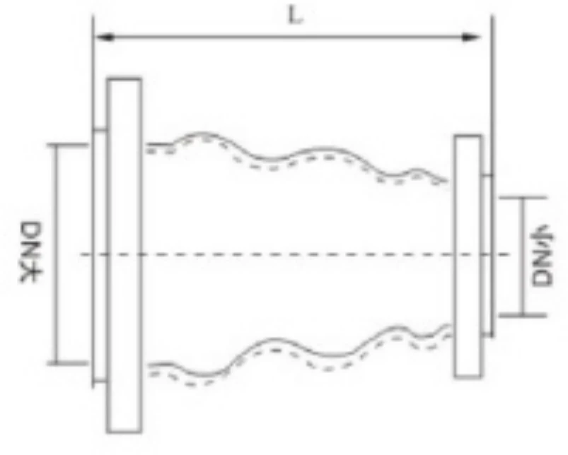
How to Specify a Reducing Rubber Joint — DN1 × DN2, Flow Direction & Length
A reducing rubber joint must be specified with two nominal diameters, not one. Use the format DN1 × DN2—for example, DN200 × DN150—and state the intended flow direction, flange standard at each end, working pressure, medium, temperature and required face-to-face length.
For hydraulic or process review, identify whether flow is DN200 → DN150 or DN150 → DN200. If pressure loss, head loss, velocity or cavitation review is required, also provide flow rate, pipe ID or schedule and system conditions. No Cv, loss coefficient or pressure-drop value is inferred on this page.
JDX Catalog Dimensions — 48 DN1×DN2 Combinations
The 48 rows below reproduce Mingchao Catalog printed page 07, physical PDF page 9 left.
| DN1 | DN2 | L_mm | Axial_Extension_mm | Axial_Compression_mm | Lateral_Displacement_mm | Angular_Deflection_deg |
|---|---|---|---|---|---|---|
| 50 | 32 | 180 | 20 | 30 | 45 | 35 |
| 50 | 40 | 180 | 20 | 30 | 45 | 35 |
| 65 | 40 | 180 | 20 | 30 | 45 | 35 |
| 65 | 50 | 180 | 20 | 30 | 45 | 35 |
| 80 | 40 | 180 | 20 | 30 | 45 | 35 |
| 80 | 50 | 180 | 20 | 30 | 45 | 35 |
| 80 | 65 | 180 | 20 | 30 | 45 | 35 |
| 100 | 40 | 180 | 20 | 30 | 45 | 35 |
| 100 | 50 | 180 | 20 | 30 | 45 | 35 |
| 100 | 65 | 180 | 22 | 30 | 45 | 35 |
| 100 | 80 | 180 | 22 | 30 | 45 | 35 |
| 125 | 50 | 200 | 22 | 30 | 45 | 35 |
| 125 | 65 | 200 | 22 | 30 | 45 | 35 |
| 125 | 80 | 200 | 22 | 30 | 45 | 35 |
| 125 | 100 | 200 | 22 | 30 | 45 | 35 |
| 150 | 50 | 200 | 22 | 30 | 45 | 35 |
| 150 | 65 | 200 | 22 | 30 | 45 | 35 |
| 150 | 80 | 200 | 22 | 30 | 45 | 35 |
| 150 | 100 | 200 | 22 | 30 | 45 | 35 |
| 150 | 125 | 200 | 22 | 30 | 45 | 35 |
| 200 | 80 | 200 | 22 | 30 | 40 | 30 |
| 200 | 100 | 200 | 22 | 30 | 40 | 30 |
| 200 | 125 | 200 | 25 | 30 | 40 | 30 |
| 200 | 150 | 200 | 25 | 35 | 40 | 30 |
| 250 | 125 | 220 | 25 | 35 | 40 | 30 |
| 250 | 150 | 220 | 25 | 35 | 40 | 30 |
| 250 | 200 | 220 | 25 | 35 | 40 | 30 |
| 300 | 125 | 220 | 25 | 35 | 40 | 30 |
| 300 | 150 | 220 | 25 | 35 | 40 | 30 |
| 300 | 200 | 220 | 25 | 35 | 40 | 30 |
| 300 | 250 | 220 | 25 | 35 | 40 | 30 |
| 350 | 150 | 240 | 25 | 35 | 40 | 30 |
| 350 | 200 | 240 | 28 | 38 | 35 | 26 |
| 350 | 250 | 240 | 28 | 38 | 35 | 26 |
| 350 | 300 | 240 | 25 | 35 | 40 | 30 |
| 400 | 200 | 240 | 25 | 35 | 40 | 30 |
| 400 | 250 | 240 | 28 | 38 | 40 | 30 |
| 400 | 300 | 240 | 28 | 38 | 40 | 30 |
| 400 | 350 | 240 | 28 | 38 | 40 | 30 |
| 450 | 300 | 240 | 28 | 38 | 40 | 30 |
| 450 | 350 | 240 | 28 | 38 | 40 | 30 |
| 450 | 400 | 240 | 28 | 38 | 40 | 30 |
| 500 | 350 | 240 | 28 | 38 | 40 | 30 |
| 500 | 400 | 240 | 28 | 38 | 40 | 30 |
| 500 | 450 | 240 | 28 | 38 | 40 | 30 |
| 600 | 400 | 240 | 28 | 38 | 40 | 30 |
| 600 | 450 | 240 | 28 | 38 | 40 | 30 |
| 600 | 500 | 240 | 28 | 38 | 40 | 30 |
Catalog movement values are individual reference values. Combined movement conditions should be reviewed against the actual operating requirement.
Extended Reducing-Joint Engineering Specification Matrix
| Engineering_Field | Published_Value | Status |
|---|---|---|
| Large-End DN | See 48-row catalog table | Source-supported |
| Small-End DN | See 48-row catalog table | Source-supported |
| Large-End NPS | Provide or confirm | Project-specific |
| Small-End NPS | Provide or confirm | Project-specific |
| Geometry | Concentric / common centerline | Source-supported |
| Flow Direction | Declare DN1 → DN2 or DN2 → DN1 | Project-specific |
| Face-to-Face Length | See catalog table or approved drawing | Source-supported / custom |
| Large-End Flange Standard | According to selected standard or drawing | Custom to approved drawing |
| Small-End Flange Standard | According to selected standard or drawing | Custom to approved drawing |
| Large-End Pressure Class | Project-specific | Engineering review required |
| Small-End Pressure Class | Project-specific | Engineering review required |
| Large-End Flange OD | According to approved drawing | Custom to approved drawing |
| Small-End Flange OD | According to approved drawing | Custom to approved drawing |
| Large-End PCD / Bolt Circle | According to approved drawing | Custom to approved drawing |
| Small-End PCD / Bolt Circle | According to approved drawing | Custom to approved drawing |
| Large-End Bolt Quantity | According to approved drawing | Custom to approved drawing |
| Small-End Bolt Quantity | According to approved drawing | Custom to approved drawing |
| Large-End Bolt-Hole Diameter / Thread | According to approved drawing | Custom to approved drawing |
| Small-End Bolt-Hole Diameter / Thread | According to approved drawing | Custom to approved drawing |
| Large-End Flange Thickness | According to approved drawing | Custom to approved drawing |
| Small-End Flange Thickness | According to approved drawing | Custom to approved drawing |
| Working Pressure | Factory confirmation required | Factory confirmation required |
| Peak / Surge Pressure | Declare in RFQ | Engineering review required |
| Hydrostatic / Test Pressure | Project-specific | Factory confirmation required |
| Burst Pressure | Factory confirmation required | Factory confirmation required |
| Vacuum Requirement | Declare in RFQ | Engineering review required |
| Operating Temperature | Declare in RFQ | Engineering review required |
| Pressure-Temperature Derating | Project-specific engineering review | Factory confirmation required |
| Axial Extension | See catalog table | Source-supported |
| Axial Compression | See catalog table | Source-supported |
| Lateral Movement | See catalog table | Source-supported |
| Angular Deflection | See catalog table | Source-supported |
| Combined Movement | Engineering review required | Factory confirmation required |
| Medium | Declare fluid and concentration | Project-specific |
| Inner Elastomer | Selected for service condition | Project-specific |
| Outer Elastomer | Selected for environment | Project-specific |
| Reinforcement Construction | Factory confirmation required | Factory confirmation required |
| Large-End Flange Material | According to project specification | Custom to approved drawing |
| Small-End Flange Material | According to project specification | Custom to approved drawing |
| Coating / Surface Protection | According to environment | Custom to approved drawing |
| Weight | Factory confirmation required | Factory confirmation required |
| Effective Area / Thrust Factor | Engineering calculation on request | Calculation on request |
| Axial Spring Rate | Engineering calculation on request | Calculation on request |
| Lateral Spring Rate | Engineering calculation on request | Calculation on request |
| Anti-Pull-Off / Control Rods | Available for project review | Engineering review required |
| Customer Drawing / CAD | Preferred for non-catalog configuration | Custom workflow |
| Inspection Requirement | Specify in RFQ | Project-specific |
| Test Requirement | Specify in RFQ | Project-specific |
| Documentation Requirement | Specify in RFQ | Project-specific |
| Project Standard / Specification | Provide with RFQ | Project-specific |
The field structure covers both connection ends independently. Fields without a verified numeric source remain project-specific, drawing-based, calculation-on-request or factory-confirmation items.
Axial, Lateral & Angular Movement
The catalog publishes axial extension, axial compression, lateral displacement and angular deflection for each DN pair. These are individual reference values, not a declaration that all four maxima can occur simultaneously.
Catalog movement values are individual reference values. Combined movement conditions should be reviewed against the actual operating requirement.
Large-End & Small-End Flange Standards — Independent Custom Drilling
The large-end and small-end flange drilling can be reviewed independently to match the connected piping or equipment. For example, one end may follow EN PN16 while the other follows an ASME Class 150 or approved equipment drawing, provided the exact interface dimensions are confirmed.
Flange drilling and pressure-class designation define the connection interface. The allowable working pressure of the complete reducing rubber expansion joint must be confirmed against the DN pair, elastomer, reinforcement, temperature, movement and operating condition.
See the Mingchao Standards Hub for existing flange-dimension resources; selected dimensions still require confirmation against the order or approved drawing.
Elastomer & Material Selection
| Elastomer | Typical Service Consideration | Selection Note |
|---|---|---|
| EPDM | Water, hot water, wastewater, HVAC and outdoor service | Oil and fuel compatibility must be confirmed |
| NBR | Oil, diesel, lubricating oil and oily media | Temperature, ozone and exact medium must be confirmed |
| NR | General water, seawater and mild abrasive media | Not universal for oil, elevated temperature or aggressive chemicals |
| CR / Neoprene | Seawater, outdoor and mild-oil environments | Exact chemical compatibility remains project-specific |
| FKM / Viton | Demanding chemical, oil or elevated-temperature service | Exact medium, concentration, temperature and pressure must be confirmed |
Material compatibility must be confirmed against the actual medium, concentration, temperature and pressure. No WRAS, NSF, ACS, FDA, food-grade or drinking-water approval is claimed.
Custom DN Pairs, Lengths & Drawing-Based Fabrication
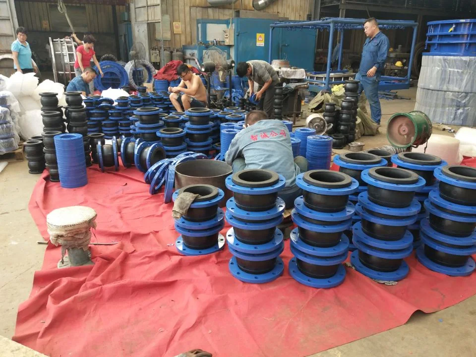
Mingchao supports drawing-based custom fabrication for the large-end and small-end diameters, face-to-face length, flange drilling at each end, bolt pattern, materials, coating, elastomer and restraint details. Non-catalog DN combinations can be reviewed and manufactured to the approved customer or project drawing, subject to engineering and manufacturability review.
Custom DN1/DN2 pairs, PCD, flange dimensions, different standards at each end and CAD/PDF workflows are available. Custom geometry does not establish unrestricted pressure, temperature or movement performance.
Pressure Thrust, Anchors, Supports & Anti-Pull-Off Devices
Internal pressure produces axial thrust that must be resisted by the piping restraint system. For larger JDX sizes and demanding pressure or high-rise service, anchors, fixed supports and any anti-pull-off or control-rod arrangement should be reviewed as part of the piping design.
The Page 07 catalog specifically notes fixed support or anti-pull-off protection above DN200 in high-pressure or high-rise conditions. It does not provide universal anchor spacing, guide distance, rod size or load.
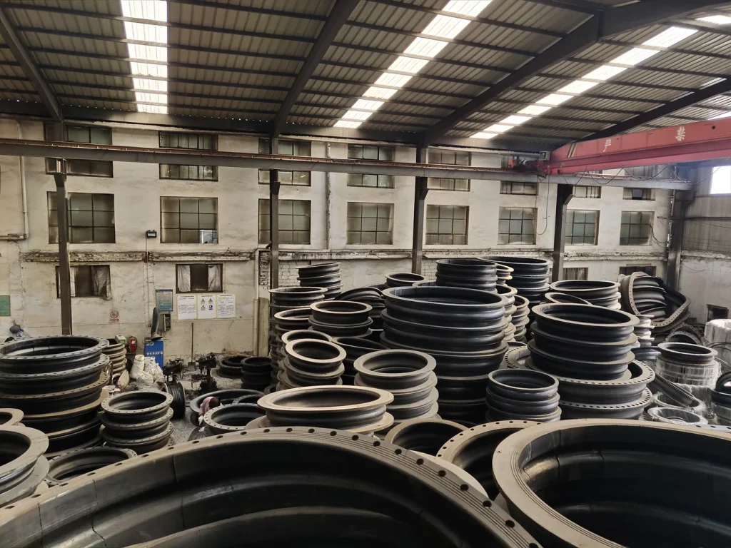
Pump, Equipment & Different-Diameter Piping Applications
JDX may be considered for pump discharge connections, pump suction connections where the design permits, different-size equipment nozzles, water-supply and treatment systems, HVAC and district cooling, industrial utilities, process-water piping, replacement work and flexible diameter transitions.
Concentric geometry is not automatically correct for every pump suction arrangement. Flow direction, drainage, trapped-air risk, solids, support and equipment requirements must be reviewed by the piping designer.
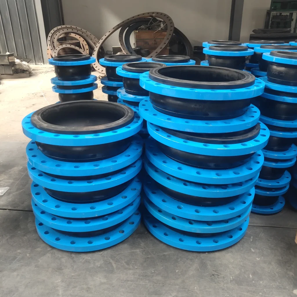
Concentric vs. Eccentric Reducing Rubber Expansion Joints
JDX uses concentric geometry: the large and small ends share one centerline. An eccentric reducing rubber expansion joint offsets those centerlines.
Selection depends on piping layout, pump configuration, drainage, trapped-air risk, solids and installation space. The eccentric reducing configuration is available as a separate product.
JDX Reducer vs. Standard Equal-Diameter Rubber Expansion Joint
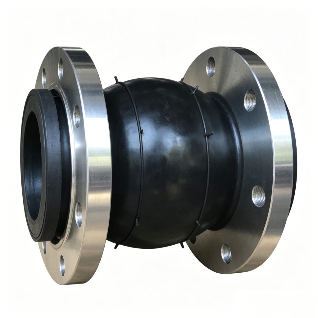
JDX connects different nominal diameters. The KXT single-sphere and KST double-sphere pages own equal-diameter flexible-connection intent.
In suitable layouts, JDX can combine the diameter transition and flexible connection in one assembly. Whether this is preferable to a separate rigid reducer and equal-diameter expansion joint depends on the piping arrangement and engineering requirements.
Inspection, Drawings & Project RFQ
Send DN1 × DN2, Flange Details & Drawing for Engineering Review.
For quotation, provide both diameters, flow direction, independent flange details, pressure, temperature, medium, face-to-face length, movement, restraint, drawing and quantity. Combinations outside the 48 catalog pairs can be reviewed from the approved drawing.
Current Chinese reference standards for flexible rubber joints include GB/T 26121-2010 and HG/T 2289-2017. CJ/T 208-2005 is also relevant to applicable urban water-supply use. Applicable manufacturing, testing and documentation requirements are confirmed against the project specification and order; these are reference standards, not JDX certification claims.
- Large-End DN / NPS
- Small-End DN / NPS
- Flow Direction
- Face-to-Face Length
- Large-End Flange Standard
- Small-End Flange Standard
- Large-End Pressure Class
- Small-End Pressure Class
- Large-End Flange OD if replacement
- Small-End Flange OD
- Large-End PCD
- Small-End PCD
- Large-End Bolt Quantity
- Small-End Bolt Quantity
- Large-End Hole Diameter / Thread
- Small-End Hole Diameter / Thread
- Flange Thickness if required
- Working Pressure
- Maximum / Surge Pressure
- Required Test Pressure
- Operating Temperature
- Medium
- Chemical Concentration
- Vacuum Requirement
- Axial Extension
- Axial Compression
- Lateral Movement
- Angular Movement
- Combined Movement
- Elastomer
- Flange Material
- Coating
- Anti-Pull-Off / Control Rod Requirement
- Anchor / Support Arrangement
- Flow Rate if hydraulic review required
- Pipe ID / Schedule if relevant
- Indoor / Outdoor
- Corrosive / Salt Environment
- Inspection Requirement
- Documentation Requirement
- Quantity
- Project Location
- Existing Drawing
- CAD
- Existing product measurements for replacement
- Destination Port / Delivery Location
Product Photos
Technical Datasheet
JDX Concentric Reducing Rubber Expansion Joint
Technical Datasheet · PDF